ADZS-BF527-EZLITE Analog Devices Inc, ADZS-BF527-EZLITE Datasheet - Page 13
ADZS-BF527-EZLITE
Manufacturer Part Number
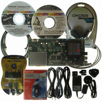
ADZS-BF527-EZLITE
Description
BOARD EVAL ADSP-BF527
Manufacturer
Analog Devices Inc
Series
Blackfin®r
Type
DSPr
Datasheet
1.ADZS-BF527-EZLITE.pdf
(80 pages)
Specifications of ADZS-BF527-EZLITE
Featured Product
Blackfin® BF50x Series Processors
Contents
Evaluation Board
Silicon Manufacturer
Analog Devices
Core Architecture
Blackfin
Features
USB-based, PC-hosted Tool Set
Silicon Core Number
ADSP-BF527
Silicon Family Name
Blackfin
Rohs Compliant
Yes
Lead Free Status / RoHS Status
Lead free / RoHS Compliant
For Use With/related Products
ADSP-BF527
Lead Free Status / RoHS Status
Lead free / RoHS Compliant, Lead free / RoHS Compliant


Preliminary Technical Data
default. Each general-purpose port pin can be individually con-
trolled by manipulation of the port control, status, and interrupt
registers:
PARALLEL PERIPHERAL INTERFACE (PPI)
The processor provides a parallel peripheral interface (PPI) that
can connect directly to parallel A/D and D/A converters, video
encoders and decoders, and other general-purpose peripherals.
The PPI consists of a dedicated input clock pin, up to three
frame synchronization pins, and up to 16 data pins. The input
clock supports parallel data rates up to half the system clock rate
and the synchronization signals can be configured as either
inputs or outputs.
The PPI supports a variety of general-purpose and ITU-R 656
modes of operation. In general-purpose mode, the PPI provides
half-duplex, bidirectional data transfer with up to 16 bits of
data. Up to three frame synchronization signals are also pro-
vided. In ITU-R 656 mode, the PPI provides half-duplex
bidirectional transfer of 8- or 10-bit video data. Additionally,
on-chip decode of embedded start-of-line (SOL) and start-of-
field (SOF) preamble packets is supported.
• GPIO direction control register – Specifies the direction of
• GPIO control and status registers – The processor employs
• GPIO interrupt mask registers – The two GPIO interrupt
• GPIO interrupt sensitivity registers – The two GPIO inter-
each individual GPIO pin as input or output.
a “write one to modify” mechanism that allows any combi-
nation of individual GPIO pins to be modified in a single
instruction, without affecting the level of any other GPIO
pins. Four control registers are provided. One register is
written in order to set pin values, one register is written in
order to clear pin values, one register is written in order to
toggle pin values, and one register is written in order to
specify a pin value. Reading the GPIO status register allows
software to interrogate the sense of the pins.
mask registers allow each individual GPIO pin to function
as an interrupt to the processor. Similar to the two GPIO
control registers that are used to set and clear individual
pin values, one GPIO interrupt mask register sets bits to
enable interrupt function, and the other GPIO interrupt
mask register clears bits to disable interrupt function.
GPIO pins defined as inputs can be configured to generate
hardware interrupts, while output pins can be triggered by
software interrupts.
rupt sensitivity registers specify whether individual pins are
level- or edge-sensitive and specify—if edge-sensitive—
whether just the rising edge or both the rising and falling
edges of the signal are significant. One register selects the
type of sensitivity, and one register selects which edges are
significant for edge-sensitivity.
Rev. PrG | Page 13 of 80 | February 2009
General-Purpose Mode Descriptions
The general-purpose modes of the PPI are intended to suit a
wide variety of data capture and transmission applications.
Three distinct submodes are supported:
Input Mode
Input mode is intended for ADC applications, as well as video
communication with hardware signaling. In its simplest form,
PPI_FS1 is an external frame sync input that controls when to
read data. The PPI_DELAY MMR allows for a delay (in
PPI_CLK cycles) between reception of this frame sync and the
initiation of data reads. The number of input data samples is
user programmable and defined by the contents of the
PPI_COUNT register. The PPI supports 8-bit and 10-bit
through 16-bit data, programmable in the PPI_CONTROL
register.
Frame Capture Mode
Frame capture mode allows the video source(s) to act as a slave
(for frame capture for example). The ADSP-BF522/524/526 and
ADSP-BF523/525/527 processors control when to read from the
video source(s). PPI_FS1 is an HSYNC output and PPI_FS2 is a
VSYNC output.
Output Mode
Output mode is used for transmitting video or other data with
up to three output frame syncs. Typically, a single frame sync is
appropriate for data converter applications, whereas two or
three frame syncs could be used for sending video with hard-
ware signaling.
ITU-R 656 Mode Descriptions
The ITU-R 656 modes of the PPI are intended to suit a wide
variety of video capture, processing, and transmission applica-
tions. Three distinct submodes are supported:
Active Video Mode
Active video only mode is used when only the active video por-
tion of a field is of interest and not any of the blanking intervals.
The PPI does not read in any data between the end of active
video (EAV) and start of active video (SAV) preamble symbols,
or any data present during the vertical blanking intervals. In this
mode, the control byte sequences are not stored to memory;
they are filtered by the PPI. After synchronizing to the start of
Field 1, the PPI ignores incoming samples until it sees an SAV
code. The user specifies the number of active video lines per
frame (in PPI_COUNT register).
1. Input mode – Frame syncs and data are inputs into the PPI.
2. Frame capture mode – Frame syncs are outputs from the
3. Output mode – Frame syncs and data are outputs from the
1. Active video only mode
2. Vertical blanking only mode
3. Entire field mode
PPI, but data are inputs.
PPI.
ADSP-BF522/523/524/525/526/527
Related parts for ADZS-BF527-EZLITE
Image
Part Number
Description
Manufacturer
Datasheet
Request
R

Part Number:
Description:
BOARD EVAL MEDIA PLAYER BF527
Manufacturer:
Analog Devices Inc
Datasheet:

Part Number:
Description:
BOARD DAUGHT ADSP-BF533,37,61KIT
Manufacturer:
Analog Devices Inc

Part Number:
Description:
BLACKFIN EZ-EXTENDER Board For ADSP-BF533/61 EZ-KIT LITE
Manufacturer:
Analog Devices Inc

Part Number:
Description:
±1.7g Dual-Axis IMEMS Accelerometer Evaluation Board
Manufacturer:
Analog Devices Inc
Datasheet:

Part Number:
Description:
Inertial Sensor Evaluation System
Manufacturer:
Analog Devices Inc
Datasheet:
Part Number:
Description:
Manufacturer:
Analog Devices Inc
Datasheet:
Part Number:
Description:
Manufacturer:
Analog Devices Inc
Datasheet:
Part Number:
Description:
Manufacturer:
Analog Devices Inc
Datasheet:
Part Number:
Description:
Manufacturer:
Analog Devices Inc
Datasheet:
Part Number:
Description:
Manufacturer:
Analog Devices Inc
Datasheet:
Part Number:
Description:
Manufacturer:
Analog Devices Inc
Datasheet:
Part Number:
Description:
Manufacturer:
Analog Devices Inc
Datasheet:
Part Number:
Description:
Manufacturer:
Analog Devices Inc
Datasheet: