ADZS-BF527-EZLITE Analog Devices Inc, ADZS-BF527-EZLITE Datasheet - Page 7
ADZS-BF527-EZLITE
Manufacturer Part Number
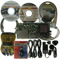
ADZS-BF527-EZLITE
Description
BOARD EVAL ADSP-BF527
Manufacturer
Analog Devices Inc
Series
Blackfin®r
Type
DSPr
Datasheet
1.ADZS-BF527-EZLITE.pdf
(80 pages)
Specifications of ADZS-BF527-EZLITE
Featured Product
Blackfin® BF50x Series Processors
Contents
Evaluation Board
Silicon Manufacturer
Analog Devices
Core Architecture
Blackfin
Features
USB-based, PC-hosted Tool Set
Silicon Core Number
ADSP-BF527
Silicon Family Name
Blackfin
Rohs Compliant
Yes
Lead Free Status / RoHS Status
Lead free / RoHS Compliant
For Use With/related Products
ADSP-BF527
Lead Free Status / RoHS Status
Lead free / RoHS Compliant, Lead free / RoHS Compliant


Preliminary Technical Data
controller to prioritize and control all system events. Conceptu-
ally, interrupts from the peripherals enter into the SIC and are
then routed directly into the general-purpose interrupts of the
CEC.
Core Event Controller (CEC)
The CEC supports nine general-purpose interrupts (IVG15–7),
in addition to the dedicated interrupt and exception events. Of
these general-purpose interrupts, the two lowest-priority
interrupts (IVG15–14) are recommended to be reserved for
software interrupt handlers, leaving seven prioritized interrupt
inputs to support the peripherals of the processor.
describes the inputs to the CEC, identifies their names in the
event vector table (EVT), and lists their priorities.
System Interrupt Controller (SIC)
The system interrupt controller provides the mapping and rout-
ing of events from the many peripheral interrupt sources to the
prioritized general-purpose interrupt inputs of the CEC.
Although the processor provides a default mapping, the user
can alter the mappings and priorities of interrupt events by writ-
ing the appropriate values into the interrupt assignment
registers (SIC_IARx).
and the default mappings into the CEC.
Table 3. System Interrupt Controller (SIC)
Peripheral Interrupt Event
PLL Wakeup Interrupt
DMA Error 0 (generic)
DMAR0 Block Interrupt
DMAR1 Block Interrupt
DMAR0 Overflow Error
DMAR1 Overflow Error
PPI Error
MAC Status
SPORT0 Status
SPORT1 Status
Reserved
Reserved
UART0 Status
UART1 Status
RTC
DMA Channel 0 (PPI/NFC)
DMA 3 Channel (SPORT0 RX)
DMA 4 Channel (SPORT0 TX)
DMA 5 Channel (SPORT1 RX)
DMA 6 Channel (SPORT1 TX)
TWI
DMA 7 Channel (SPI)
DMA8 Channel (UART0 RX)
DMA9 Channel (UART0 TX)
Table 3
describes the inputs into the SIC
General Purpose
Interrupt (at RESET) Peripheral Interrupt ID
IVG7
IVG7
IVG7
IVG7
IVG7
IVG7
IVG7
IVG7
IVG7
IVG7
IVG7
IVG7
IVG7
IVG7
IVG8
IVG8
IVG9
IVG9
IVG9
IVG9
IVG10
IVG10
IVG10
IVG10
Rev. PrG | Page 7 of 80 | February 2009
Table 2
0
1
2
3
4
5
6
7
8
9
10
11
12
13
14
15
16
17
18
19
20
21
22
23
Table 2. Core Event Controller (CEC)
Priority
(0 is Highest)
0
1
2
3
4
5
6
7
8
9
10
11
12
13
14
15
ADSP-BF522/523/524/525/526/527
Default
Core Interrupt ID SIC Registers
0
0
0
0
0
0
0
0
0
0
0
0
0
0
1
1
2
2
2
2
3
3
3
3
Event Class
Emulation/Test Control
RESET
Nonmaskable Interrupt
Exception
Reserved
Hardware Error
Core Timer
General-Purpose Interrupt 7
General-Purpose Interrupt 8
General-Purpose Interrupt 9
General-Purpose Interrupt 10
General-Purpose Interrupt 11
General-Purpose Interrupt 12
General-Purpose Interrupt 13
General-Purpose Interrupt 14
General-Purpose Interrupt 15
IAR0
IAR0
IAR0
IAR0
IAR0
IAR0
IAR0
IAR0
IAR1
IAR1
IAR1
IAR1
IAR1
IAR1
IAR1
IAR1
IAR2
IAR2
IAR2
IAR2
IAR2
IAR2
IAR2
IAR2
IMASK0, ISR0, IWR0
IMASK0, ISR0, IWR0
IMASK0, ISR0, IWR0
IMASK0, ISR0, IWR0
IMASK0, ISR0, IWR0
IMASK0, ISR0, IWR0
IMASK0, ISR0, IWR0
IMASK0, ISR0, IWR0
IMASK0, ISR0, IWR0
IMASK0, ISR0, IWR0
IMASK0, ISR0, IWR0
IMASK0, ISR0, IWR0
IMASK0, ISR0, IWR0
IMASK0, ISR0, IWR0
IMASK0, ISR0, IWR0
IMASK0, ISR0, IWR0
IMASK0, ISR0, IWR0
IMASK0, ISR0, IWR0
IMASK0, ISR0, IWR0
IMASK0, ISR0, IWR0
IMASK0, ISR0, IWR0
IMASK0, ISR0, IWR0
IMASK0, ISR0, IWR0
IMASK0, ISR0, IWR0
EVT Entry
EMU
RST
NMI
EVX
—
IVHW
IVTMR
IVG7
IVG8
IVG9
IVG10
IVG11
IVG12
IVG13
IVG14
IVG15
Related parts for ADZS-BF527-EZLITE
Image
Part Number
Description
Manufacturer
Datasheet
Request
R

Part Number:
Description:
BOARD EVAL MEDIA PLAYER BF527
Manufacturer:
Analog Devices Inc
Datasheet:

Part Number:
Description:
BOARD DAUGHT ADSP-BF533,37,61KIT
Manufacturer:
Analog Devices Inc

Part Number:
Description:
BLACKFIN EZ-EXTENDER Board For ADSP-BF533/61 EZ-KIT LITE
Manufacturer:
Analog Devices Inc

Part Number:
Description:
±1.7g Dual-Axis IMEMS Accelerometer Evaluation Board
Manufacturer:
Analog Devices Inc
Datasheet:

Part Number:
Description:
Inertial Sensor Evaluation System
Manufacturer:
Analog Devices Inc
Datasheet:
Part Number:
Description:
Manufacturer:
Analog Devices Inc
Datasheet:
Part Number:
Description:
Manufacturer:
Analog Devices Inc
Datasheet:
Part Number:
Description:
Manufacturer:
Analog Devices Inc
Datasheet:
Part Number:
Description:
Manufacturer:
Analog Devices Inc
Datasheet:
Part Number:
Description:
Manufacturer:
Analog Devices Inc
Datasheet:
Part Number:
Description:
Manufacturer:
Analog Devices Inc
Datasheet:
Part Number:
Description:
Manufacturer:
Analog Devices Inc
Datasheet:
Part Number:
Description:
Manufacturer:
Analog Devices Inc
Datasheet: