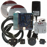
C8051F326DK Silicon Laboratories Inc, C8051F326DK Datasheet - Page 3

C8051F326DK
Manufacturer Part Number
C8051F326DK
Description
KIT DEV FOR C8051F326/7
Manufacturer
Silicon Laboratories Inc
Type
MCUr
Specifications of C8051F326DK
Contents
Evaluation Board, Power Supply, USB Cables, Adapter and Documentation
Processor To Be Evaluated
C8051F326/F327
Interface Type
USB
Silicon Manufacturer
Silicon Labs
Core Architecture
8051
Silicon Core Number
C8051F326
Silicon Family Name
C8051F32x
Lead Free Status / RoHS Status
Contains lead / RoHS non-compliant
For Use With/related Products
Silicon Laboratories C8051F326, C8051F327
Lead Free Status / Rohs Status
Lead free / RoHS Compliant
Other names
336-1306
Table of Contents
1. System Overview.................................................................................................... 13
2. Absolute Maximum Ratings .................................................................................. 23
3. Global DC Electrical Characteristics .................................................................... 24
4. Pinout and Package Definitions............................................................................ 25
5. Voltage Regulator (REG0)...................................................................................... 31
6. CIP-51 Microcontroller .......................................................................................... 35
7. Reset Sources ....................................................................................................... 57
1.1. CIP-51™ Microcontroller Core.......................................................................... 17
1.2. On-Chip Memory............................................................................................... 19
1.3. Universal Serial Bus Controller ......................................................................... 20
1.4. Voltage Regulator ............................................................................................. 20
1.5. On-Chip Debug Circuitry................................................................................... 21
1.6. Programmable Digital I/O.................................................................................. 22
1.7. Serial Ports ....................................................................................................... 22
5.1. Regulator Mode Selection................................................................................. 31
5.2. VBUS Detection ................................................................................................ 31
6.1. Instruction Set ................................................................................................... 36
6.2. Memory Organization........................................................................................ 41
6.3. Interrupt Handler ............................................................................................... 48
6.4. Power Management Modes .............................................................................. 55
7.1. Power-On Reset ............................................................................................... 58
7.2. Power-Fail Reset / VDD Monitor....................................................................... 59
7.3. External Reset .................................................................................................. 60
7.4. Missing Clock Detector Reset........................................................................... 60
1.1.1. Fully 8051 Compatible.............................................................................. 17
1.1.2. Improved Throughput ............................................................................... 17
1.1.3. Additional Features .................................................................................. 18
6.1.1. Instruction and CPU Timing ..................................................................... 36
6.1.2. MOVX Instruction and Program Memory ................................................. 37
6.2.1. Program Memory...................................................................................... 41
6.2.2. Data Memory............................................................................................ 42
6.2.3. General Purpose Registers ...................................................................... 42
6.2.4. Bit Addressable Locations........................................................................ 42
6.2.5. Stack ....................................................................................................... 42
6.2.6. Special Function Registers....................................................................... 43
6.2.7. Register Descriptions ............................................................................... 45
6.3.1. MCU Interrupt Sources and Vectors ........................................................ 48
6.3.2. External Interrupts .................................................................................... 49
6.3.3. Interrupt Priorities ..................................................................................... 49
6.3.4. Interrupt Latency ...................................................................................... 49
6.3.5. Interrupt Register Descriptions................................................................. 50
6.4.1. Idle Mode.................................................................................................. 55
6.4.2. Stop Mode ................................................................................................ 55
Rev. 1.1
C8051F326/7
3


