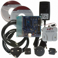
C8051F326DK Silicon Laboratories Inc, C8051F326DK Datasheet - Page 72

C8051F326DK
Manufacturer Part Number
C8051F326DK
Description
KIT DEV FOR C8051F326/7
Manufacturer
Silicon Laboratories Inc
Type
MCUr
Specifications of C8051F326DK
Contents
Evaluation Board, Power Supply, USB Cables, Adapter and Documentation
Processor To Be Evaluated
C8051F326/F327
Interface Type
USB
Silicon Manufacturer
Silicon Labs
Core Architecture
8051
Silicon Core Number
C8051F326
Silicon Family Name
C8051F32x
Lead Free Status / RoHS Status
Contains lead / RoHS non-compliant
For Use With/related Products
Silicon Laboratories C8051F326, C8051F327
Lead Free Status / Rohs Status
Lead free / RoHS Compliant
Other names
336-1306
C8051F326/7
10.1.1. Adjusting the Internal Oscillator on C8051F326/7 Devices
The OSCICL reset value is factory calibrated to result in a 12 MHz internal oscillator with a ±1.5% accu-
racy; this frequency is suitable for use as the USB clock (see Section “10.5. System and USB Clock Selec-
tion” on page 76). Software may adjust the frequency of the internal oscillator using the OSCICL register.
Important Note: Once the internal oscillator frequency has been modified, the internal oscillator may not
be used as the USB clock as described in Section “10.5. System and USB Clock Selection” on page 76.
The internal oscillator frequency will reset to its original factory-calibrated frequency following any device
reset, at which point the oscillator is suitable for use as the USB clock.
10.1.2. Internal Oscillator Suspend Mode
The internal oscillator may be placed in Suspend mode by writing ‘1’ to the SUSPEND bit in register
OSCICN. In Suspend mode, the internal oscillator is stopped until a non-idle USB event is detected (Sec-
tion “12. Universal Serial Bus Controller (USB0)” on page 87) or VBUS matches the polarity selected by
the VBPOL bit in register REG0CN (Section “5.2. VBUS Detection” on page 31). Note that the USB trans-
ceiver must be enabled or in Suspend mode for a USB event to be detected.
72
Bit7:
Bit6:
Bit5:
Bits4–2: Unused. Read = 000b. Write = don't care.
Bits1–0: IFCN1–0: Internal Oscillator Frequency Control Bits.
IOSCEN
R/W
Bit7
IOSCEN: Internal Oscillator Enable Bit.
0: Internal Oscillator Disabled.
1: Internal Oscillator Enabled.
IFRDY: Internal Oscillator Frequency Ready Flag.
0: Internal Oscillator is not running at programmed frequency.
1: Internal Oscillator is running at programmed frequency.
SUSPEND: Force Suspend
Writing a ‘1’ to this bit will force the internal oscillator to be stopped. The oscillator will be re-
started on the next non-idle USB event (i.e., RESUME signaling) or VBUS interrupt event
(see SFR Definition 5.1).
00: SYSCLK derived from Internal Oscillator divided by 8.
01: SYSCLK derived from Internal Oscillator divided by 4.
10: SYSCLK derived from Internal Oscillator divided by 2.
11: SYSCLK derived from Internal Oscillator divided by 1.
IFRDY
SFR Definition 10.1. OSCICN: Internal Oscillator Control
Bit6
R
SUSPEND
R/W
Bit5
Bit4
—
R
Rev. 1.1
R/W
Bit3
—
R/W
Bit2
—
IFCN1
R/W
Bit1
IFCN0
R/W
Bit0
SFR Address:
Reset Value
11000000
0xB2


