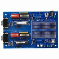
CY3220LINBUS-RD Cypress Semiconductor Corp, CY3220LINBUS-RD Datasheet - Page 25

CY3220LINBUS-RD
Manufacturer Part Number
CY3220LINBUS-RD
Description
KIT REF DESIGN LIN BUS
Manufacturer
Cypress Semiconductor Corp
Series
PSoC®r
Datasheet
1.CY3220LINBUS-RD.pdf
(64 pages)
Specifications of CY3220LINBUS-RD
Main Purpose
Interface, LIN
Embedded
Yes, MCU, 8-Bit
Utilized Ic / Part
CY8C27143, CY8C27443
Processor To Be Evaluated
CY8C27143-24PXI and CY8C27443-24PXI
Interface Type
RS-232
Lead Free Status / RoHS Status
Contains lead / RoHS non-compliant
Lead Free Status / RoHS Status
Lead free / RoHS Compliant, Contains lead / RoHS non-compliant
Other names
428-1926
LIN Bus 2.0 Reference Design
3.6.11.2
Here is an example Schedule table. The name of the table is
Schedule1. This table has Frame1, Frame2, Frame3 and
Frame4 (which are defined in the SignalTable.asm file) in
the order they are entered in the Schedule table.
Schedule table example:
_Schedule1:
dw Frame1, 20
dw Frame3, 10
dw Frame2, 10
dw Frame4, 10
dw 0xFFFF
The last entry in the Schedule table is the table terminator.
When the l_sch_tick function comes across 0xFFFF, it goes
back to the start of the Schedule table.
3.6.11.3
In addition to the user-defined Schedule tables defined in
the LDF, there are some tables defined in the API that are
available for other diagnostic functions. They are listed
below.
■
■
■
These schedules are at the end of ScheduleTable.asm file.
Set these tables using the l_sch_set function before calling
the node configuration functions or the l_goto_sleep func-
tion.
Once the Schedule table definitions are done, export the
schedule names so that they are referenced by the LIN
functions and the main program. This is done in the begin-
ning of the ScheduleTable.asm file.
; Export Schedule Names
export _L_NULL_SCHEDULE
export
export _Schedule1
export
export _ScheduleNodeConfiguration
export
export _ScheduleGoToSleep
export
Then declare these names in the ScheduleTable.h file so
that these schedules are referenced in the C program.
// Definition of Schedule Names to be used in
the main program.
extern const char L_NULL_SCHEDULE[];
extern const char Schedule1[];
extern const char ScheduleNodeConfigura-
tion[];
extern const char ScheduleGoToSleep[];
October 25, 2006
Schedule1:
ScheduleNodeConfiguration: This schedule contains
a master request frame and a slave response frame.
ScheduleGoToSleep: This schedule contains a master-
request frame.
L_NULL_SCHEDULE: This schedule is null and does
not transmit any frame.
L_NULL_SCHEDULE
Schedule1
ScheduleNodeConfiguration
ScheduleGoToSleep
An Example Schedule Table
Diagnostic Schedules
Cypress Semiconductor – Rev. **
3.6.12
Now that the LIN 2.0 master is configured, you can add the
main application. Follow the normal procedure of building an
application using PSoC Designer. Place the user modules in
the base configuration, finish the routing, and generate the
application.
In the main.c file, follow these steps to properly start the LIN
firmware and update the LIN frames.
1. Call the l_ifc_init function to initialize the LIN function.
2. Enable the Global Interrupts using the M8C_EnableGInt
3. Write a 0 to the first byte of all the frame buffers. This is
4. Perform node configuration if necessary.
5. Set the schedule that the master must follow.
6. Inside an infinite loop, add the application code.
■
■
■
The example main file given in section 5,
Projects on page
fer.
3.6.13
3.6.13.1
For power management there are some functions available
in the LinPowerManagement.c file.
A. ShutdownLin: This function properly stops all the active
B. SleepLoop: When this function is entered, the
macro.
to clear the status bytes of the buffers.
Keep checking for a completion of transaction of each
frame using the bfLAST_TRANSACTION_OK flag on
the first byte of the frame buffer, then process the data.
If polling is used to initiate a frame transfer, use the
LinMaster_fIsLinReady function to check if the current
time slot is over before calling the l_sch_tick function.
If using an interrupt-driven frame transfer, then call the
l_sch_tick function inside the ScheduleTimer_ISR func-
tion found in the FrameTiming.c file.
LIN resources and makes the pins HighZ so that the pro-
cessor enters a low power state. Inside this function,
there is an area into which the user must enter code to
stop all the resources used by the main application.
Also, if the main application uses analog resources, turn
off the analog reference and the analog buffers to mini-
mize current consumption during sleep state. It also dis-
ables all the interrupts except the GPIO interrupt. Call
this function to put the master in power-down mode after
it executes the l_goto_sleep function putting all the
slaves in the cluster to power-down mode.
M8C_Sleep macro is executed to put the processor to
sleep. Once the processor is put to sleep, it wakes up
only upon an interrupt. Since all interrupts are disabled
except the GPIO interrupt, when a slave in the cluster
issues a wakeup command (dominant state for a time of
250 µs to 5 ms), the processor wakes up and enters a
loop where it waits for the bus to go to recessive state.
When this happens, it checks the length of the dominant
state. If this length is within a specified limit, it returns
Adding the Main Application
Special Features
Low Power Management
43, uses the polling method of frame trans-
3. Master Design IP
Demonstration
23


