CY3220LINBUS-RD Cypress Semiconductor Corp, CY3220LINBUS-RD Datasheet - Page 33
CY3220LINBUS-RD
Manufacturer Part Number
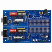
CY3220LINBUS-RD
Description
KIT REF DESIGN LIN BUS
Manufacturer
Cypress Semiconductor Corp
Series
PSoC®r
Datasheet
1.CY3220LINBUS-RD.pdf
(64 pages)
Specifications of CY3220LINBUS-RD
Main Purpose
Interface, LIN
Embedded
Yes, MCU, 8-Bit
Utilized Ic / Part
CY8C27143, CY8C27443
Processor To Be Evaluated
CY8C27143-24PXI and CY8C27443-24PXI
Interface Type
RS-232
Lead Free Status / RoHS Status
Contains lead / RoHS non-compliant
Lead Free Status / RoHS Status
Lead free / RoHS Compliant, Contains lead / RoHS non-compliant
Other names
428-1926


4.1
4.1.1
The software architecture maximizes interrupt processing to
minimize the processing overhead on the end application.
All processing of the current message using the configura-
tions is performed at the interrupt level. Each stage is
designed as a state machine and at completion, unloads
itself and loads in the next required configuration to propa-
gate the message to completion via LIN message protocol
sequence. Each processed message is identified by the
identifier byte in the header. The identifier is defined by the
agreed master-slave relationship in the LIN description file
(LDF). See the example LDF in section 5,
File (LDF) on page
Each slave node establishes a message table that defines
the set of identifiers that it will process. The slave has two
such tables. One is the Message ID table and the other is
the Protected ID table. For each entry in the Message ID
table, there is an associated entry in the Protected ID table.
This table has details of protected ID, data direction (TX or
RX), event-triggered frames, data count, and the pointer to
the buffer to receive data into or transmit data from. Initially,
when the device is programmed, the protected ID for each
entry is made 0xFF. When the node is connected to a LIN
cluster and when node configuration is carried out, the pro-
tected IDs are updated with the configured values.
For an identifier that specifies the receipt of data, the slave
device places the data received in the associated buffer. For
an identifier that specifies the transmission of data, the slave
device transmits the data to the LIN bus at the baud rate
used by the master, from the associated data buffer. For
slave-to-slave communication facilitated by the master
device, an agreed upon identifier causes a transmit
response from one slave and receive response from another
slave. Update the data buffers for each frame in the fore-
ground process by the main application. This is done by
using the corresponding core API functions. The first byte of
each data buffer is used as a status byte for the frame. This
byte is used by event-triggered frames to indicate if a signal
was updated and if the frame must be sent. In diagnostic
frames, this byte is used to indicate whether or not to trans-
mit a slave response.
October 25, 2006
4.
Slave Design IP
Software Architecture
Overview
43.
LIN Description
Cypress Semiconductor – Rev. **
4.1.2
The main process must initialize the LIN function and then
perform the actual application. The main process should
continuously read the status of the LIN transaction using the
l_read_status function and check if a frame was received
from the master and process accordingly. The foreground
process is to update the frames to transmit. It also should
check if the go to sleep flag was set by the LIN firmware. If
yes, it needs to switch off all the resources and enter the
sleep state. Functions for entering sleep state and waiting
for the wakeup call from the master are provided in the Low-
PowerManagement.c file.
4.1.3
Because automotive applications are often real-time driven,
the LIN driver only makes use of interrupts, with no active
loop or blocking functions. Overhead measurements made
on a LIN bus with messages transferred at 19200 bauds and
PSoC CPU running at 24 MHz, show a 0% overhead
between messages, and a maximum overhead of 8% while
sending or receiving messages. Refer to
page 40
The LIN slave design leverages interrupts to maximize idle
time between transmitted and received data bits. When the
LIN bus is idle, no LIN slave associated interrupts are
invoked. When the LIN master initiates a message protocol,
the slave GPIO interrupt is triggered to initiate the reception
and processing of the LIN message transmitted on the bus.
At a minimum, all LIN slaves synchronize to the synch break
header and receive the identifier. For slaves in which the
identifier requires action, the specific slave responds appro-
priately as agreed to by the definition of the identifier byte. In
slaves for whom the identifier does not require any action,
the following bytes of the frame are received and discarded.
When the frame completion is detected by a receiver time-
out, the slaves are re-initialized to receive the break field of
the next frame. This minimal interrupt consumes less than
3% of CPU overhead. Since the LIN bus is asynchronous,
for details.
Foreground Processing
Timing and Interrupts
Time Study on
31
Related parts for CY3220LINBUS-RD
Image
Part Number
Description
Manufacturer
Datasheet
Request
R

Part Number:
Description:
KIT DEMO PSOC CAPSENSE
Manufacturer:
Cypress Semiconductor Corp
Datasheet:

Part Number:
Description:
KIT DEMO PSOC CAPSENSE SLIDE
Manufacturer:
Cypress Semiconductor Corp

Part Number:
Description:
Manufacturer:
Cypress Semiconductor Corp
Datasheet:
Part Number:
Description:
Manufacturer:
Cypress Semiconductor Corp
Datasheet:
Part Number:
Description:
Manufacturer:
Cypress Semiconductor Corp
Datasheet:
Part Number:
Description:
Manufacturer:
Cypress Semiconductor Corp
Datasheet:
Part Number:
Description:
Manufacturer:
Cypress Semiconductor Corp
Datasheet: