CY3220LINBUS-RD Cypress Semiconductor Corp, CY3220LINBUS-RD Datasheet - Page 7
CY3220LINBUS-RD
Manufacturer Part Number
CY3220LINBUS-RD
Description
KIT REF DESIGN LIN BUS
Manufacturer
Cypress Semiconductor Corp
Series
PSoC®r
Datasheet
1.CY3220LINBUS-RD.pdf
(64 pages)
Specifications of CY3220LINBUS-RD
Main Purpose
Interface, LIN
Embedded
Yes, MCU, 8-Bit
Utilized Ic / Part
CY8C27143, CY8C27443
Processor To Be Evaluated
CY8C27143-24PXI and CY8C27443-24PXI
Interface Type
RS-232
Lead Free Status / RoHS Status
Contains lead / RoHS non-compliant
Lead Free Status / RoHS Status
Lead free / RoHS Compliant, Contains lead / RoHS non-compliant
Other names
428-1926


1.1
1.1.1
The LIN Bus Demonstration Kit demonstrates the ability of
the PSoC® Programmable System-on-Chip™ to implement
LIN bus, Local Interconnect Network, standard protocol. The
LIN bus was developed to fill the need for a low cost auto-
motive network to complement existing networks. LIN bus
also finds many uses in non-automotive distributed systems
where a robust, low-speed and low-cost protocol is required.
Additional information is located on the LIN consortium web
site at
complete LIN specifications for version 2.0.
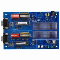
This design provides a flexible development environment for
creation of either slave or master LIN device applications
using the PSoC. The demonstration board has one master
and two slave nodes. Using dynamic reconfiguration, hard-
ware resources are minimized with low CPU overhead.
Design details on specific implementation provided with the
demonstration board are included in the supplied Lin Master
Node Design IP, Lin Slave Design IP, Application Note
AN2045, and in the corresponding project comments inside
PSoC Designer™.
1.2
■
■
■
■
October 25, 2006
1.
LIN Bus Demonstration Board
International Power Supply (110-220 VAC to 12V DC)
Serial Cable (DB-9)
Software CD with Documentation, Example Project, and
Design IP
http://www.lin-subbus.org
LIN Bus 2.0 Kit
LIN Bus 2.0 Demonstration Kit Description
Kit Contents
Introduction
where you can also find the
Cypress Semiconductor – Rev. **
1.3
The LIN bus demonstration board is preprogrammed to
demonstrate the LIN bus directly out of the box. To demon-
strate functionality, follow these steps:
1. Verify contents in design kit.
2. Plug the power supply into a wall outlet (international
3. Connect the barrel plug of the power supply cord into the
The demonstration board is now fully operational and dem-
onstrates LIN bus operations. Functional details of the
examples running on the board can be found in section 1.4,
LIN Bus Demonstration, on page
plug adaptors are included). The power supply automati-
cally adapts to this voltage and frequency range: 100-
240 VAC at 50-60 Hz.
demonstration board. The green power LED next to the
power jack lights.
Getting Started
6.
5
Related parts for CY3220LINBUS-RD
Image
Part Number
Description
Manufacturer
Datasheet
Request
R

Part Number:
Description:
KIT DEMO PSOC CAPSENSE
Manufacturer:
Cypress Semiconductor Corp
Datasheet:

Part Number:
Description:
KIT DEMO PSOC CAPSENSE SLIDE
Manufacturer:
Cypress Semiconductor Corp

Part Number:
Description:
Manufacturer:
Cypress Semiconductor Corp
Datasheet:
Part Number:
Description:
Manufacturer:
Cypress Semiconductor Corp
Datasheet:
Part Number:
Description:
Manufacturer:
Cypress Semiconductor Corp
Datasheet:
Part Number:
Description:
Manufacturer:
Cypress Semiconductor Corp
Datasheet:
Part Number:
Description:
Manufacturer:
Cypress Semiconductor Corp
Datasheet: