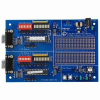
CY3220LINBUS-RD Cypress Semiconductor Corp, CY3220LINBUS-RD Datasheet - Page 36

CY3220LINBUS-RD
Manufacturer Part Number
CY3220LINBUS-RD
Description
KIT REF DESIGN LIN BUS
Manufacturer
Cypress Semiconductor Corp
Series
PSoC®r
Datasheet
1.CY3220LINBUS-RD.pdf
(64 pages)
Specifications of CY3220LINBUS-RD
Main Purpose
Interface, LIN
Embedded
Yes, MCU, 8-Bit
Utilized Ic / Part
CY8C27143, CY8C27443
Processor To Be Evaluated
CY8C27143-24PXI and CY8C27443-24PXI
Interface Type
RS-232
Lead Free Status / RoHS Status
Contains lead / RoHS non-compliant
Lead Free Status / RoHS Status
Lead free / RoHS Compliant, Contains lead / RoHS non-compliant
Other names
428-1926
4. Slave Design IP
■
4.3.6
When the protected ID is decoded inside the RX ISR and
the slave has to transmit a response to the master or to
another slave, the Data Transmission Configuration is
loaded. (This is not a physical reloadable configuration, but
a re-organization of the Data Reception Configuration in the
firmware to transmit a slave response.) For CY8C27x43 and
CY8C29x66 device families, a separate digital block is used
for TX. To reduce digital block usage in the CY8C21x34
design, the same digital block used for RX is reconfigured
into TX.
The RX ISR also updates the data counter and the buffer
pointer. The TX8 interrupt is enabled and the first byte of the
response is written to the TX buffer. At this time, the bit time
counter is initialized to generate an interrupt every bit time.
This interrupt is used to check if the TX and RX bits are the
same. After this, every time the TX buffer is empty, an inter-
rupt is generated and the next byte of the response is writ-
ten to the TX buffer. When all the bytes have been sent, the
LastByteSent flag is set.
4.3.7
The bit time interrupt is used in both the data reception and
data transmission states.
Data Reception: When data reception is taking place, the
bit time counter is configured to generate an interrupt every
five bit times. Inside the ISR, a timeout counter is decre-
mented. This timeout counter is initialized in the protected
ID decode function after finding out the number of bytes to
be received. This value is 1.4 times the actual number of bits
to receive. So during normal operation, before this counter
becomes zero, the frame completes and the Synchro
Reception Configuration is loaded by the RX ISR. But if, due
to some fault, the bus activity stops and after the set number
of bits the timeout counter becomes zero, the Synchro
Reception Configuration is loaded.
Data Transmission: When data transmission is underway,
this ISR is used to detect bit errors. The bit time counter is
configured to generate an interrupt every bit time. When the
interrupt is generated, the state of the TX and RX pins is
34
the Synchro Reception Configuration is loaded to
receive the next frame.
Waiting for Frame Completion: If, in the first step of
decoding the protected ID, it is found that the ID is not
present in the ID table, then the node should wait for the
present frame to complete. Every time a data is received
on the bus (either from master or from some other
node), a timeout counter is initialized to 15. The received
data is discarded. The timeout counter will be decre-
mented inside the bit time counter ISR. When this count
becomes zero, it means that no data have been received
for 15 bit times, which in turn indicates that the current
frame is completed and the Synchro Reception Configu-
ration is loaded inside the bit time counter ISR to wait for
the next frame.
TX Interrupt
Bit Timer Interrupt
Cypress Semiconductor – Rev. **
compared. If the states are the same, then there is no bit
error. But if these two pins are at a different states, there is a
bit error. Upon detection of the bit error, the TX8 User Mod-
ule is stopped and the Synchro Reception Configuration is
loaded.
4.4
Lin20CoreAPI.asm: This file contains the functions for the
LIN core APIs.
Lin20PhysicalLayer.asm: This file contains the code
related to the proper operation of the LIN firmware. It has all
the ISRs described in section 4.3,
MathUtilities.asm: This file has the math functions used by
the LIN firmware.
RamVariables.asm: This file contains the variable alloca-
tions.
SignalTable.asm: This file has the Message table and the
Protected ID table. It must be modified according to the
specifications in the LDF.
LinPowerManagement.c: This file has the functions that
are required for the go to sleep and wakeup operations of
LIN.
4.5
Lin20CoreAPI.h: This file contains the function prototypes
for the Lin20CoreAPI.asm file.
Lin20Defines.h: This file has the variable types defined in
the LIN specifications.
Lin20Slave.h: This file has the definitions of different con-
stants and flags used in the firmware.
LinPowerManagement.h: This file has the function proto-
types used by the LinPowerManagement.c file.
SignalTable.h: This file has declarations of the signal buff-
ers and frame names used in the SignalTable.asm file.
Lin20Slave.inc: This file contains the definitions of all the
constants and flags used by the Lin20PhysicalLayer.asm
file.
NodeInformation.inc: This file has definitions of constants
relating to the product ID of the node. Such constants
include serial number, product ID, manufacturer’s ID, vari-
ant, number of messages supported by node, etc.
When using the source code and header files, modify the
following files according to information in the LDF.
SignalTable.asm
SignalTable.h
NodeInformation.inc
LIN Source Code Files
Header Files
LIN Bus 2.0 Reference Design
Firmware on page
October 25, 2006
32.


