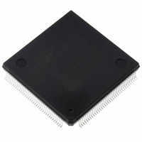
ST10F269Z2Q6 STMicroelectronics, ST10F269Z2Q6 Datasheet - Page 64

ST10F269Z2Q6
Manufacturer Part Number
ST10F269Z2Q6
Description
MCU 16BIT 256K FLASH 144PQFP
Manufacturer
STMicroelectronics
Series
ST10r
Specifications of ST10F269Z2Q6
Core Processor
ST10
Core Size
16-Bit
Speed
40MHz
Connectivity
CAN, EBI/EMI, SSC, UART/USART
Peripherals
POR, PWM, WDT
Number Of I /o
111
Program Memory Size
256KB (256K x 8)
Program Memory Type
FLASH
Ram Size
12K x 8
Voltage - Supply (vcc/vdd)
4.5 V ~ 5.5 V
Data Converters
A/D 16x10b
Oscillator Type
Internal
Operating Temperature
-40°C ~ 85°C
Package / Case
144-QFP
Controller Family/series
ST10
No. Of I/o's
111
Ram Memory Size
12KB
Cpu Speed
40MHz
No. Of Timers
5
Embedded Interface Type
CAN, SSC, USART
Rohs Compliant
Yes
Processor Series
ST10F26x
Core
ST10
Data Bus Width
16 bit
Data Ram Size
12 KB
Interface Type
CAN, SSC, USART
Maximum Clock Frequency
40 MHz
Number Of Programmable I/os
111
Number Of Timers
2 x 16 bit
Operating Supply Voltage
0.3 V to 4 V
Maximum Operating Temperature
+ 85 C
Mounting Style
SMD/SMT
Minimum Operating Temperature
- 40 C
On-chip Adc
16 bit x 10 bit
Lead Free Status / RoHS Status
Lead free / RoHS Compliant
Eeprom Size
-
Lead Free Status / Rohs Status
Details
Other names
497-4833
Available stocks
Company
Part Number
Manufacturer
Quantity
Price
Company:
Part Number:
ST10F269Z2Q6
Manufacturer:
ST
Quantity:
201
Company:
Part Number:
ST10F269Z2Q6
Manufacturer:
ST
Quantity:
745
Company:
Part Number:
ST10F269Z2Q6
Manufacturer:
STMicroelectronics
Quantity:
10 000
Part Number:
ST10F269Z2Q6
Manufacturer:
ST
Quantity:
20 000
12 - PARALLEL PORTS
12.3.1 - Alternate Functions of PORT0
When an external bus is enabled, PORT0 is used
as data bus or address/data bus.
Note that an external 8-bit demultiplexed bus only
uses P0L, while P0H is free for I/O (provided that
no other bus mode is enabled).
PORT0 is also used to select the system start-up
configuration. During reset, PORT0 is configured
to input, and each line is held high through an
internal pull-up device.
Each line can now be individually pulled to a low
level (see Section 21.3 -: DC Characteristics)
through an external pull-down device. A default
configuration is selected when the respective
PORT0 lines are at a high level. Through pulling
individual lines to a low level, this default can be
changed
applications.
The internal pull-up devices are designed in such
way that an external pull-down resistors (see Data
Sheet specification) can be used to apply a
correct low level.
These external pull-down resistors can remain
connected to the PORT0 pins also during normal
operation, however, care has to be taken in order
to not disturb the normal function of PORT0 (this
might be the case, for example, if the external
resistor value is too low).
Figure 21 : PORT0 I/O and Alternate Functions
64/184
PORT0
General Purpose
Alternate Function
P0H
P0L
Input/Output
according
P0H.7
P0H.6
P0H.5
P0H.4
P0H.3
P0H.2
P0H.1
P0H.0
P0L.7
P0L.6
P0L.5
P0L.4
P0L.3
P0L.2
P0L.1
P0L.0
to
the
Demultiplexed Bus
needs
8-bit
a)
D7
D6
D5
D4
D3
D2
D1
D0
of
the
Demultiplexed Bus
16-bit
b)
With the end of reset, the selected bus
configuration will be written to the BUSCON0
register.
The configuration of the high byte of PORT0, will
be copied into the special register RP0H. This
read-only register holds the selection for the
number of chip selects and segment addresses.
Software can read this register in order to react
according
required.
When the reset is terminated, the internal pull-up
devices are switched off, and PORT0 will be
switched to the appropriate operating mode.
During external accesses in multiplexed bus
modes
intra-segment address as an alternate output
function.
high-impedance input mode to read the incoming
instruction or data. In 8-bit data bus mode, two
memory cycles are required for word accesses,
the first for the low Byte and the second for the
high Byte of the Word.
During write cycles PORT0 outputs the data Byte
or Word after outputting the address. During
external accesses in demultiplexed bus modes
PORT0 reads the incoming instruction or data
Word or outputs the data Byte or Word.
D15
D14
D13
D12
D11
D10
D9
D8
D7
D6
D5
D4
D3
D2
D1
D0
PORT0
Multiplexed Bus
PORT0
to
c)
8-bit
the
first
A15
A14
A13
A12
A11
A10
A9
A8
AD7
AD6
AD5
AD4
AD3
AD2
AD1
AD0
selected
is
outputs
then
Multiplexed Bus
configuration,
16-bit
d)
switched
ST10F269
the
AD15
AD14
AD13
AD12
AD11
AD10
AD9
AD8
AD7
AD6
AD5
AD4
AD3
AD2
AD1
AD0
16-bit
to
if


