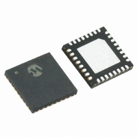
MRF89XA-I/MQ Microchip Technology, MRF89XA-I/MQ Datasheet - Page 60

MRF89XA-I/MQ
Manufacturer Part Number
MRF89XA-I/MQ
Description
TXRX ISM SUB-GHZ ULP 32QFN
Manufacturer
Microchip Technology
Specifications of MRF89XA-I/MQ
Package / Case
32-WFQFN Exposed Pad
Frequency
863MHz ~ 870MHz, 902MHz ~ 928MHz, 950MHz ~ 960MHz
Data Rate - Maximum
200kbps
Modulation Or Protocol
FSK, OOK
Applications
ISM
Power - Output
12.5dBm
Sensitivity
-113dBm
Voltage - Supply
2.1 V ~ 3.6 V
Current - Receiving
3mA
Current - Transmitting
25mA
Data Interface
PCB, Surface Mount
Antenna Connector
PCB, Surface Mount
Operating Temperature
-40°C ~ 85°C
Number Of Receivers
1
Number Of Transmitters
1
Wireless Frequency
863 MHz to 870 MHz, 902 MHz to 928 MHz, 950 MHz to 960 MHz
Interface Type
SPI
Noise Figure
- 112 dBc
Output Power
- 8.5 dBm, + 12.5 dBm
Operating Supply Voltage
2.1 V to 3.6 V
Maximum Operating Temperature
+ 85 C
Mounting Style
SMD/SMT
Maximum Data Rate
256 Kbps
Maximum Supply Current
25 mA
Minimum Operating Temperature
- 40 C
Modulation
FSK
Lead Free Status / RoHS Status
Lead free / RoHS Compliant
Memory Size
-
Lead Free Status / Rohs Status
Lead free / RoHS Compliant
Available stocks
Company
Part Number
Manufacturer
Quantity
Price
Company:
Part Number:
MRF89XA-I/MQ
Manufacturer:
MICROCHIP
Quantity:
12 000
3.1
A power-on reset of the MRF89XA is triggered at power
up. Additionally, a manual reset can be issued by
controlling the TEST8 pin (pin 13).
3.1.1
If the application requires the disconnection of V
from the MRF89XA, the user should wait for 10 ms
from the end of the POR cycle before commencing
communications using SPI. The TEST8 pin should be
left floating during the POR sequence. Figure 3-2 illus-
trates the POR Timing..
FIGURE 3-2:
FIGURE 3-3:
DS70622B-page 60
MRF89XA
Note:
Reset of the Chip
POWER-ON RESET (POR)
Any CLKOUT-related activity can also be
used to detect that the chip is ready.
Pin 13
(input)
V
DD
Pin 13
(output)
V
POR TIMING DIAGRAM
MANUAL RESET TIMING DIAGRAM
DD
Undefined
High-Z
> 100 µs
Wait for
10 ms
Preliminary
DD
1
Chip is ready from this point forward
High-Z
Wait for
5 ms
3.1.2
A manual reset of the MRF89XA is possible even for
applications in which V
disconnected. The TEST8 pin should be pulled high for
100 u (micro) and then released. The user should then
wait 5 ms before using the chip. The pin is driven with
an open-drain output, and therefore, is pulled high
while the device is in POR. Figure 3-3 illustrates the
Manual Reset Timing
Note:
Chip is ready from this point forward
MANUAL RESET
When the TEST8 pin is driven high, an
current consumption of up to 10 mA can
be seen on V
© 2010 Microchip Technology Inc.
DD
DD
.
cannot be physically


