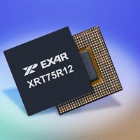
XRT75R12DIB-F Exar Corporation, XRT75R12DIB-F Datasheet - Page 77

XRT75R12DIB-F
Manufacturer Part Number
XRT75R12DIB-F
Description
Peripheral Drivers & Components (PCIs) 12 Channel 3.3V-5V temp -45 to 85C
Manufacturer
Exar Corporation
Datasheet
1.XRT75R12DIB-F.pdf
(133 pages)
Specifications of XRT75R12DIB-F
Maximum Operating Temperature
+ 85 C
Minimum Operating Temperature
- 40 C
Mounting Style
SMD/SMT
Operating Supply Voltage
3.3 V to 5 V
Package / Case
TBGA-420
Lead Free Status / RoHS Status
Lead free / RoHS Compliant
- Current page: 77 of 133
- Download datasheet (851Kb)
A
REV. 1.0.3
B
LARM
IT
N
5
4
UMBER
S
TATUS
TWELVE CHANNEL E3/DS3/STS-1 LINE INTERFACE UNIT WITH SONET DESYNCHRONIZER
Analog LOS Defect
Digital LOS Defect
R
EGISTER
Declared
Declared
N
AME
- C
HANNEL N
T
R/O
R/O
YPE
A
DDRESS
Digital LOS Defect Declared:
This READ-ONLY bit-field indicates whether or not the Digital LOS (Loss of
Signal) detector is declaring the LOS Defect condition.
For DS3 and STS-1 applications, the Digital LOS Detector will declare the
LOS Defect condition whenever it detects an absence of pulses (within the
incoming DS3 or STS-1 data-stream) for 160 consecutive bit-periods.
Further, (again for DS3 and STS-1 applications) the Digital LOS Detector will
clear the LOS Defect condition whenever it determines that the pulse density
(within the incoming DS3 or STS-1 signal) is at least 33%.
0 - Indicates that the Digital LOS Detector is NOT declaring the LOS Defect
Condition.
1 - Indicates that the Digital LOS Detector is currently declaring the LOS
Defect condition.
N
Analog LOS Defect Declared:
This READ-ONLY bit-field indicates whether or not the Analog LOS (Loss of
Signal) detector is declaring the LOS Defect condition.
For DS3 and STS-1 applications, the Analog LOS Detector will declare the
LOS Defect condition whenever it determines that the amplitude of the
pulses (within the incoming DS3/STS-1 line signal) drops below a certain
Analog LOS Defect Declaration threshold level.
Conversely, (again for DS3 and STS-1 applications) the Analog LOS Detec-
tor will clear the LOS Defect condition whenever it determines that the ampli-
tude of the pulses (within the incoming DS3/STS-1 line signal) has risen
above a certain Analog LOS Defect Clearance threshold level.
It should be noted that, in order to prevent "chattering" within the Analog
LOS Detector output, there is some built-in hysteresis between the Analog
LOS Defect Declaration and the Analog LOS Defect Clearance threshold
levels.
0 - Indicates that the Analog LOS Detector is NOT declaring the LOS Defect
Condition.
1 - Indicates that the Analog LOS Detector is currently declaring the LOS
Defect condition.
N
OTES
OTES
1. LOS Detection (within each channel of the XRT75R12D) is
2. The current LOS Defect Condition (for the channel) can be
1. LOS Detection (within each channel of the XRT75R12D) is
2. The current LOS Defect Condition (for the channel) can be
:
:
L
performed by both an Analog LOS Detector and a Digital LOS
Detector. The LOS state of a given Channel is simply a WIRED-
OR of the LOS Defect Declare states of these two detectors.
determined by reading out the contents of Bit 1 (Receive LOS
Defect Declared) within this register.
performed by both an Analog LOS Detector and a Digital LOS
Detector. The LOS state of a given Channel is simply a WIRED-
OR of the LOS Defect Declare states of these two detectors.
determined by reading out the contents of Bit 1 (Receive LOS
Defect Declared) within this register.
OCATION
73
= 0
XM
3 (
M
= 0-5 & 8-D)
D
ESCRIPTION
XRT75R12D
Related parts for XRT75R12DIB-F
Image
Part Number
Description
Manufacturer
Datasheet
Request
R

Part Number:
Description:
Twelve Channel E3/ds3/sts-1 Line Interface Unit With Jitter
Manufacturer:
Exar Corporation
Datasheet:

Part Number:
Description:
BiCMOS Fixed, Quad, Voltage Output, Single or Dual Supply 8-Bit Digital-to-Analog Converter
Manufacturer:
Exar Corporation
Datasheet:

Part Number:
Description:
Manufacturer:
Exar Corporation
Datasheet:

Part Number:
Description:
Voltage-Controlled Oscillator
Manufacturer:
Exar Corporation
Datasheet:

Part Number:
Description:
INTEGRATED LINE TRANSMITTER
Manufacturer:
Exar Corporation
Datasheet:

Part Number:
Description:
Monolithic Function Generator
Manufacturer:
Exar Corporation
Datasheet:

Part Number:
Description:
CMOS Microprocessor Compatible Double-Buffered 12-Bit Digital-to-Analog Converter
Manufacturer:
Exar Corporation
Datasheet:

Part Number:
Description:
CMOS 6 BIT HIGH SPEED ANALOG TO DIGITAL CONVERTER
Manufacturer:
Exar Corporation
Datasheet:

Part Number:
Description:
Manufacturer:
Exar Corporation
Datasheet:

Part Number:
Description:
Manufacturer:
Exar Corporation
Datasheet:

Part Number:
Description:
8-Channel, Voltage Output 10 MHz Input Bandwidth 8-Bit Multiplying DACs with Serial Digital Data Por
Manufacturer:
Exar Corporation
Datasheet:

Part Number:
Description:
15 V CMOS Multiplying10-Bit Digital-to-Analog Converter
Manufacturer:
Exar Corporation
Datasheet:

Part Number:
Description:
Monolithic Function Generator
Manufacturer:
Exar Corporation
Datasheet:


