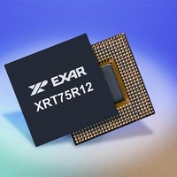
XRT75R12DIB-F Exar Corporation, XRT75R12DIB-F Datasheet - Page 94

XRT75R12DIB-F
Manufacturer Part Number
XRT75R12DIB-F
Description
Peripheral Drivers & Components (PCIs) 12 Channel 3.3V-5V temp -45 to 85C
Manufacturer
Exar Corporation
Datasheet
1.XRT75R12DIB-F.pdf
(133 pages)
Specifications of XRT75R12DIB-F
Maximum Operating Temperature
+ 85 C
Minimum Operating Temperature
- 40 C
Mounting Style
SMD/SMT
Operating Supply Voltage
3.3 V to 5 V
Package / Case
TBGA-420
Lead Free Status / RoHS Status
Lead free / RoHS Compliant
- Current page: 94 of 133
- Download datasheet (851Kb)
XRT75R12D
TWELVE CHANNEL E3/DS3/STS-1 LINE INTERFACE UNIT WITH SONET DESYNCHRONIZER
In order to be able to describe how a DS3 signal is asynchronously mapped into an STS-1 SPE, it is important
to define and understand all of the following.
An STS-1 frame is a data-structure that consists of 810 bytes (or 6480 bits). A given STS-1 frame can be
viewed as being a 9 row by 90 byte column array (making up the 810 bytes). The frame-repetition rate (for an
STS-1 frame) is 8000 frames/second. Therefore, the bit-rate for an STS-1 signal is (6480 bits/frame * 8000
frames/sec =) 51.84Mbps.
A simple illustration of this SONET STS-1 frame is presented below in
Figure 38
the extreme upper left hand corner of the 90 column by 9 row array, and that the very last byte of a given STS-
1 frame is located in the extreme lower right-hand corner of the frame structure. Whenever a Network Element
transmits a SONET STS-1 frame, it starts by transmitting all of the data, residing within the top row of the STS-
1 frame structure (beginning with the left-most byte, and then transmitting the very next byte, to the right). After
the Network Equipment has completed its transmission of the top or first row, it will then proceed to transmit the
second row of data (again starting with the left-most byte, first). Once the Network Equipment has transmitted
the last byte of a given STS-1 frame, it will proceed to start transmitting the very next STS-1 frame.
The illustration of the STS-1 frame (in
that the STS-1 frame consists of numerous types of bytes. For the sake of discussion within this data sheet,
the STS-1 frame will be described as consisting of the following types (or groups) of bytes.
The Transport Overhead or TOH bytes occupy the very first three (3) byte columns within each STS-1 frame.
Figure 39
TOH and the Envelope Capacity bytes are designated in this Figure.
F
8.2.1.1
8.2.1.1.1
IGURE
The STS-1 frame structure
The STS-1 SPE (Synchronous Payload Envelope)
Telcordia GR-253-CORE's recommendation on mapping DS3 data into an STS-1 SPE
The Transport Overheads (or TOH) Bytes
The Envelope Capacity Bytes
38. A S
indicates that the very first byte of a given STS-1 frame (to be transmitted or received) is located in
presents another simple illustration of an STS-1 frame structure. However, in this case, both the
A Brief Description of an STS-1 Frame
IMPLE
The Transport Overhead (TOH) Bytes
9 Rows
I
LLUSTRATION OF THE
First Byte of the STS-1 Frame
Figure
SONET STS-1 F
38) is very simplistic, for multiple reasons. One major reason is
STS-1 Frame (810 Bytes)
Last Byte of the STS-1 Frame
90
90 Bytes
RAME
Figure
38.
REV. 1.0.3
Related parts for XRT75R12DIB-F
Image
Part Number
Description
Manufacturer
Datasheet
Request
R

Part Number:
Description:
Twelve Channel E3/ds3/sts-1 Line Interface Unit With Jitter
Manufacturer:
Exar Corporation
Datasheet:

Part Number:
Description:
BiCMOS Fixed, Quad, Voltage Output, Single or Dual Supply 8-Bit Digital-to-Analog Converter
Manufacturer:
Exar Corporation
Datasheet:

Part Number:
Description:
Manufacturer:
Exar Corporation
Datasheet:

Part Number:
Description:
Voltage-Controlled Oscillator
Manufacturer:
Exar Corporation
Datasheet:

Part Number:
Description:
INTEGRATED LINE TRANSMITTER
Manufacturer:
Exar Corporation
Datasheet:

Part Number:
Description:
Monolithic Function Generator
Manufacturer:
Exar Corporation
Datasheet:

Part Number:
Description:
CMOS Microprocessor Compatible Double-Buffered 12-Bit Digital-to-Analog Converter
Manufacturer:
Exar Corporation
Datasheet:

Part Number:
Description:
CMOS 6 BIT HIGH SPEED ANALOG TO DIGITAL CONVERTER
Manufacturer:
Exar Corporation
Datasheet:

Part Number:
Description:
Manufacturer:
Exar Corporation
Datasheet:

Part Number:
Description:
Manufacturer:
Exar Corporation
Datasheet:

Part Number:
Description:
8-Channel, Voltage Output 10 MHz Input Bandwidth 8-Bit Multiplying DACs with Serial Digital Data Por
Manufacturer:
Exar Corporation
Datasheet:

Part Number:
Description:
15 V CMOS Multiplying10-Bit Digital-to-Analog Converter
Manufacturer:
Exar Corporation
Datasheet:

Part Number:
Description:
Monolithic Function Generator
Manufacturer:
Exar Corporation
Datasheet:


