NUMICRO-SDK Nuvoton Technology Corporation of America, NUMICRO-SDK Datasheet - Page 490
NUMICRO-SDK
Manufacturer Part Number
NUMICRO-SDK
Description
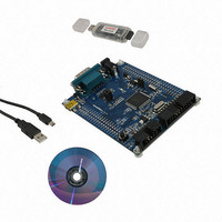
KIT EVAUATION NUC100/120/130/140
Manufacturer
Nuvoton Technology Corporation of America
Series
NuMicro™r
Type
MCUr
Datasheets
1.NUC100LC1BN.pdf
(600 pages)
2.NUMICRO-SDK.pdf
(13 pages)
3.NUMICRO-SDK.pdf
(93 pages)
4.NUMICRO-SDK.pdf
(1 pages)
Specifications of NUMICRO-SDK
Contents
Board, Cable, CD, Nu-Link
Lead Free Status / RoHS Status
Lead free / RoHS Compliant
For Use With/related Products
NUC100, NUC120, NUC130, NUC140
Available stocks
Company
Part Number
Manufacturer
Quantity
Price
Company:

Part Number:
NUMICRO-SDK
Manufacturer:
Nuvoton Technology Corporation
Quantity:
135
Company:
Part Number:
NUMICRO-SDK
Manufacturer:
NuvoTon
Quantity:
69


5.16.4.5 Continuous Scan Mode
In continuous scan mode, A/D conversion is performed sequentially on the specified channels
that enabled by CHEN bits in ADCHER register (maximum 8 channels for ADC). The operations
are as follows:
An example timing diagram for continuous scan on enabled channels (0, 2, 3 and 7) is shown as
below:
1.
2.
3.
4.
When the ADST bit in ADCR is set to 1 by software or external trigger input, A/D
conversion starts on the channel with the lowest number.
When A/D conversion for each enabled channel is completed, the result of each enabled
channel is stored in the A/D data register corresponding to each enabled channel.
When all enabled channel sequentially completes A/D converting once, the ADF bit
(ADSR[0]) will be set to 1. If the ADIE bit is set to 1 at this time, an ADC_INT interrupt is
requested after A/D conversion ends. Conversion of the 1st enabled channel starts
again.
Steps 2 to 3 are repeated as long as the ADST bit remains enable. When ADST is
cleared to 0, ADC controller will finish current conversion and the result of the lowest
enabled ADC channel will become unpredictable.
NuMicro™ NUC100 Series Technical Reference Manual
Figure 5-99 Continuous Scan on Enabled Channels Timing Diagram
- 490 -
Publication Release Date: Dec. 22, 2010
Revision V1.06
Related parts for NUMICRO-SDK
Image
Part Number
Description
Manufacturer
Datasheet
Request
R

Part Number:
Description:
IC MCU 32BIT 32KB FLASH 33QFN
Manufacturer:
Nuvoton Technology Corporation of America
Datasheet:
Part Number:
Description:
IC MCU 32BIT 32KB FLASH 48LQFP
Manufacturer:
Nuvoton Technology Corporation of America
Datasheet:

Part Number:
Description:
IC MCU 32BIT 32KB FLASH 48LQFP
Manufacturer:
Nuvoton Technology Corporation of America
Datasheet:

Part Number:
Description:
IC MCU 32BIT 64KB FLASH 33QFN
Manufacturer:
Nuvoton Technology Corporation of America
Datasheet:

Part Number:
Description:
IC MCU 32BIT 32KB FLASH 48LQFP
Manufacturer:
Nuvoton Technology Corporation of America
Datasheet:

Part Number:
Description:
IC MCU 32BIT 64KB FLASH 48LQFP
Manufacturer:
Nuvoton Technology Corporation of America
Datasheet:

Part Number:
Description:
IC MCU 32BIT 64KB FLASH 64LQFP
Manufacturer:
Nuvoton Technology Corporation of America
Datasheet:

Part Number:
Description:
IC MCU 32BIT 64KB FLASH 64LQFP
Manufacturer:
Nuvoton Technology Corporation of America
Datasheet:

Part Number:
Description:
IC MCU 32BIT 64KB FLASH 48LQFP
Manufacturer:
Nuvoton Technology Corporation of America
Datasheet:
Part Number:
Description:
IC MCU 32BIT 64KB FLASH 64LQFP
Manufacturer:
Nuvoton Technology Corporation of America
Datasheet:

Part Number:
Description:
IC MCU 32BIT 8KB FLASH 33QFN
Manufacturer:
Nuvoton Technology Corporation of America
Datasheet:

Part Number:
Description:
IC MCU 32BIT 8KB FLASH 48LQFP
Manufacturer:
Nuvoton Technology Corporation of America
Datasheet:
Part Number:
Description:
IC MCU 32BIT 16KB FLASH 33QFN
Manufacturer:
Nuvoton Technology Corporation of America
Datasheet:
Part Number:
Description:
IC MCU 32BIT 64KB FLASH 100LQFP
Manufacturer:
Nuvoton Technology Corporation of America
Datasheet:

Part Number:
Description:
IC MCU 32BIT 128KB FLASH 64LQFP
Manufacturer:
Nuvoton Technology Corporation of America
Datasheet: