NUMICRO-SDK Nuvoton Technology Corporation of America, NUMICRO-SDK Datasheet - Page 498
NUMICRO-SDK
Manufacturer Part Number
NUMICRO-SDK
Description
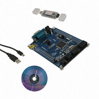
KIT EVAUATION NUC100/120/130/140
Manufacturer
Nuvoton Technology Corporation of America
Series
NuMicro™r
Type
MCUr
Datasheets
1.NUC100LC1BN.pdf
(600 pages)
2.NUMICRO-SDK.pdf
(13 pages)
3.NUMICRO-SDK.pdf
(93 pages)
4.NUMICRO-SDK.pdf
(1 pages)
Specifications of NUMICRO-SDK
Contents
Board, Cable, CD, Nu-Link
Lead Free Status / RoHS Status
Lead free / RoHS Compliant
For Use With/related Products
NUC100, NUC120, NUC130, NUC140
Available stocks
Company
Part Number
Manufacturer
Quantity
Price
Company:

Part Number:
NUMICRO-SDK
Manufacturer:
Nuvoton Technology Corporation
Quantity:
135
Company:
Part Number:
NUMICRO-SDK
Manufacturer:
NuvoTon
Quantity:
69


[10]
[9]
[8]
[7:6]
[5:4]
NuMicro™ NUC100 Series Technical Reference Manual
DIFFEN
PTEN
TRGEN
TRGCOND
TRGS
A/D Differential Input Mode Enable
1 = A/D is in differential analog input mode
0 = A/D is in single-end analog input mode
Differential input voltage (V
In differential input mode, only one of the two corresponding channels needs to be
enabled in ADCHER. The conversion result will be placed to the corresponding data
register of the enabled channel. If both channels of a differential input paired channel
are enabled, the ADC will convert it twice in scan mode. And then write the conversion
result to the two corresponding data registers.
PDMA Transfer Enable
1 = Enable PDMA data transfer in ADDR 0~7
0 = Disable PDMA data transfer
When A/D conversion is completed, the converted data is loaded into ADDR 0~7,
software can enable this bit to generate a PDMA data transfer request.
When PTEN=1, software must set ADIE=0 to disable interrupt.
External Trigger Enable
Enable or disable triggering of A/D conversion by external STADC pin.
1= Enable
0= Disable
External Trigger Condition
These two bits decide external pin STADC trigger event is level or edge. The signal
must be kept at stable state at least 8 PCLKs for level trigger and 4 PCLKs at high and
low state for edge trigger.
00 = Low level
01 = High level
10 = Falling edge
11 = Rising edge
Hardware Trigger Source
00 = A/D conversion is started by external STADC pin.
Others = Reserved
Software should disable TRGEN and ADST before change TRGS.
In hardware trigger mode, the ADST bit is set by the external trigger from STADC.
Differential input paired channel
- 498 -
0
1
2
3
diff
) = V
plus
Publication Release Date: Dec. 22, 2010
- V
minus
ADC0
ADC2
ADC4
ADC6
V
plus
ADC analog input
ADC1
ADC3
ADC5
ADC7
V
Revision V1.06
minus
Related parts for NUMICRO-SDK
Image
Part Number
Description
Manufacturer
Datasheet
Request
R

Part Number:
Description:
IC MCU 32BIT 32KB FLASH 33QFN
Manufacturer:
Nuvoton Technology Corporation of America
Datasheet:
Part Number:
Description:
IC MCU 32BIT 32KB FLASH 48LQFP
Manufacturer:
Nuvoton Technology Corporation of America
Datasheet:

Part Number:
Description:
IC MCU 32BIT 32KB FLASH 48LQFP
Manufacturer:
Nuvoton Technology Corporation of America
Datasheet:

Part Number:
Description:
IC MCU 32BIT 64KB FLASH 33QFN
Manufacturer:
Nuvoton Technology Corporation of America
Datasheet:

Part Number:
Description:
IC MCU 32BIT 32KB FLASH 48LQFP
Manufacturer:
Nuvoton Technology Corporation of America
Datasheet:

Part Number:
Description:
IC MCU 32BIT 64KB FLASH 48LQFP
Manufacturer:
Nuvoton Technology Corporation of America
Datasheet:

Part Number:
Description:
IC MCU 32BIT 64KB FLASH 64LQFP
Manufacturer:
Nuvoton Technology Corporation of America
Datasheet:

Part Number:
Description:
IC MCU 32BIT 64KB FLASH 64LQFP
Manufacturer:
Nuvoton Technology Corporation of America
Datasheet:

Part Number:
Description:
IC MCU 32BIT 64KB FLASH 48LQFP
Manufacturer:
Nuvoton Technology Corporation of America
Datasheet:
Part Number:
Description:
IC MCU 32BIT 64KB FLASH 64LQFP
Manufacturer:
Nuvoton Technology Corporation of America
Datasheet:

Part Number:
Description:
IC MCU 32BIT 8KB FLASH 33QFN
Manufacturer:
Nuvoton Technology Corporation of America
Datasheet:

Part Number:
Description:
IC MCU 32BIT 8KB FLASH 48LQFP
Manufacturer:
Nuvoton Technology Corporation of America
Datasheet:
Part Number:
Description:
IC MCU 32BIT 16KB FLASH 33QFN
Manufacturer:
Nuvoton Technology Corporation of America
Datasheet:
Part Number:
Description:
IC MCU 32BIT 64KB FLASH 100LQFP
Manufacturer:
Nuvoton Technology Corporation of America
Datasheet:

Part Number:
Description:
IC MCU 32BIT 128KB FLASH 64LQFP
Manufacturer:
Nuvoton Technology Corporation of America
Datasheet: