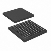
PIC32MX695F512L-80I/BG Microchip Technology, PIC32MX695F512L-80I/BG Datasheet - Page 181

PIC32MX695F512L-80I/BG
Manufacturer Part Number
PIC32MX695F512L-80I/BG
Description
IC, 32BIT MCU, PIC32, 80MHZ, BGA-100
Manufacturer
Microchip Technology
Series
PIC® 32MXr
Datasheets
1.PIC32MX320F032H-40IPT.pdf
(66 pages)
2.PIC32MX575F256H-80IMR.pdf
(2 pages)
3.PIC32MX575F256H-80IMR.pdf
(254 pages)
4.PIC32MX575F256H-80IMR.pdf
(14 pages)
5.PIC32MX575F256H-80IPT.pdf
(240 pages)
Specifications of PIC32MX695F512L-80I/BG
Controller Family/series
PIC32
Ram Memory Size
128KB
Cpu Speed
80MHz
No. Of Timers
5
Interface
I2C, SPI, UART, USB
No. Of Pwm Channels
5
Core Size
32 Bit
Program Memory Size
512 KB
Core Processor
MIPS32® M4K™
Speed
80MHz
Connectivity
Ethernet, I²C, SPI, UART/USART, USB OTG
Peripherals
Brown-out Detect/Reset, DMA, POR, PWM, WDT
Program Memory Type
FLASH
Ram Size
128K x 8
Voltage - Supply (vcc/vdd)
2.3 V ~ 3.6 V
Data Converters
A/D 16x10b
Oscillator Type
Internal
Operating Temperature
-40°C ~ 85°C
Package / Case
121-TFBGA
Embedded Interface Type
I2C, SPI, UART, USB
Rohs Compliant
Yes
Processor Series
PIC32MX6xx
Core
MIPS
3rd Party Development Tools
52713-733, 52714-737
Development Tools By Supplier
PG164130, DV164035, DV244005
Lead Free Status / RoHS Status
Lead free / RoHS Compliant
Number Of I /o
-
Eeprom Size
-
Lead Free Status / Rohs Status
Details
Available stocks
Company
Part Number
Manufacturer
Quantity
Price
Company:
Part Number:
PIC32MX695F512L-80I/BG
Manufacturer:
Microchip Technology
Quantity:
135
Company:
Part Number:
PIC32MX695F512L-80I/BG
Manufacturer:
Microchip Technology
Quantity:
10 000
- PIC32MX320F032H-40IPT PDF datasheet
- PIC32MX575F256H-80IMR PDF datasheet #2
- PIC32MX575F256H-80IMR PDF datasheet #3
- PIC32MX575F256H-80IMR PDF datasheet #4
- PIC32MX575F256H-80IPT PDF datasheet #5
- Current page: 181 of 240
- Download datasheet (3Mb)
TABLE 31-7:
2009 Microchip Technology Inc.
DC CHARACTERISTICS
Power-Down Current (I
DC40
DC40a
DC40b
DC40c
DC40d
DC40e
DC40g
DC40f
Module Differential Current
DC41
DC41c
DC41d
DC42
DC42c
DC42e
DC43
DC43c
DC43e
Note 1:
Parameter
No.
2:
3:
4:
5:
6:
Base I
is disabled. All I/Os are configured as outputs and pulled low. WDT and FSCM are disabled.
Data in the “Typical” column is at 3.3V, 25°C unless otherwise stated. Parameters are for design guidance
only and are not tested.
The current is the additional current consumed when the module is enabled. This current should be
added to the base I
Test conditions for ADC module differential current are as follows: Internal ADC RC oscillator enabled.
Data is characterized at +70°C and not tested. Parameter is for design guidance only.
This parameter is characterized, but not tested in manufacturing.
Typical
1100
400
315
410
PD
DC CHARACTERISTICS: POWER-DOWN CURRENT (I
10
36
41
22
42
23
—
—
—
—
—
—
5
is measured with all digital peripheral modules enabled (ON bit = 1 ) and being clocked, CPU clock
(2)
PD
) (Note 1)
Max.
1300
1300
100
720
120
120
400
800
PD
40
80
10
—
20
40
—
50
—
current.
Standard Operating Conditions: 2.3V to 3.6V (unless otherwise stated)
Operating temperature
Units
A
A
A
A
A
A
A
A
A
A
A
A
A
A
A
A
A
Preliminary
+25°C
+85°C
+25°C
+25°C
+70°C
+85°C
-40°C
-40°C
2.3V
3.3V
3.6V
2.3V
3.3V
3.6V
2.5V
3.3V
3.6V
PIC32MX5XX/6XX/7XX
2.3V
3.3V
3.6V
-40°C T
Watchdog Timer Current: I
A
Watchdog Timer Current: I
Watchdog Timer Current: I
RTCC + Timer1 w/32kHz Crystal: I
RTCC + Timer1 w/32kHz Crystal: I
RTCC + Timer1 w/32kHz Crystal: I
+85°C for Industrial
Base Power-Down Current (Note 6)
Conditions
PD
ADC: I
Base Power-Down Current
Base Power-Down Current
ADC: I
ADC: I
)
(Notes 3, 6)
ADC
ADC
ADC
(Note 3)
(Note 3)
(Notes 3, 4, 6)
(Notes 3, 4)
(Notes 3, 4)
DS61156B-page 181
WDT
WDT
WDT
(Notes 3, 6)
(Note 3)
(Note 3)
RTCC
RTCC
RTCC
Related parts for PIC32MX695F512L-80I/BG
Image
Part Number
Description
Manufacturer
Datasheet
Request
R

Part Number:
Description:
Manufacturer:
Microchip Technology Inc.
Datasheet:

Part Number:
Description:
Manufacturer:
Microchip Technology Inc.
Datasheet:

Part Number:
Description:
Manufacturer:
Microchip Technology Inc.
Datasheet:

Part Number:
Description:
Manufacturer:
Microchip Technology Inc.
Datasheet:

Part Number:
Description:
Manufacturer:
Microchip Technology Inc.
Datasheet:

Part Number:
Description:
Manufacturer:
Microchip Technology Inc.
Datasheet:

Part Number:
Description:
Manufacturer:
Microchip Technology Inc.
Datasheet:

Part Number:
Description:
Manufacturer:
Microchip Technology Inc.
Datasheet:


