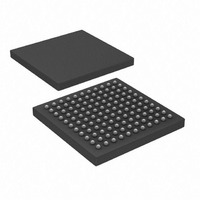
PIC32MX695F512L-80I/BG Microchip Technology, PIC32MX695F512L-80I/BG Datasheet - Page 33

PIC32MX695F512L-80I/BG
Manufacturer Part Number
PIC32MX695F512L-80I/BG
Description
IC, 32BIT MCU, PIC32, 80MHZ, BGA-100
Manufacturer
Microchip Technology
Series
PIC® 32MXr
Datasheets
1.PIC32MX320F032H-40IPT.pdf
(66 pages)
2.PIC32MX575F256H-80IMR.pdf
(2 pages)
3.PIC32MX575F256H-80IMR.pdf
(254 pages)
4.PIC32MX575F256H-80IMR.pdf
(14 pages)
5.PIC32MX575F256H-80IPT.pdf
(240 pages)
Specifications of PIC32MX695F512L-80I/BG
Controller Family/series
PIC32
Ram Memory Size
128KB
Cpu Speed
80MHz
No. Of Timers
5
Interface
I2C, SPI, UART, USB
No. Of Pwm Channels
5
Core Size
32 Bit
Program Memory Size
512 KB
Core Processor
MIPS32® M4K™
Speed
80MHz
Connectivity
Ethernet, I²C, SPI, UART/USART, USB OTG
Peripherals
Brown-out Detect/Reset, DMA, POR, PWM, WDT
Program Memory Type
FLASH
Ram Size
128K x 8
Voltage - Supply (vcc/vdd)
2.3 V ~ 3.6 V
Data Converters
A/D 16x10b
Oscillator Type
Internal
Operating Temperature
-40°C ~ 85°C
Package / Case
121-TFBGA
Embedded Interface Type
I2C, SPI, UART, USB
Rohs Compliant
Yes
Processor Series
PIC32MX6xx
Core
MIPS
3rd Party Development Tools
52713-733, 52714-737
Development Tools By Supplier
PG164130, DV164035, DV244005
Lead Free Status / RoHS Status
Lead free / RoHS Compliant
Number Of I /o
-
Eeprom Size
-
Lead Free Status / Rohs Status
Details
Available stocks
Company
Part Number
Manufacturer
Quantity
Price
Company:
Part Number:
PIC32MX695F512L-80I/BG
Manufacturer:
Microchip Technology
Quantity:
135
Company:
Part Number:
PIC32MX695F512L-80I/BG
Manufacturer:
Microchip Technology
Quantity:
10 000
- PIC32MX320F032H-40IPT PDF datasheet
- PIC32MX575F256H-80IMR PDF datasheet #2
- PIC32MX575F256H-80IMR PDF datasheet #3
- PIC32MX575F256H-80IMR PDF datasheet #4
- PIC32MX575F256H-80IPT PDF datasheet #5
- Current page: 33 of 240
- Download datasheet (3Mb)
TABLE 1-1:
2009 Microchip Technology Inc.
PGED1
PGEC1
PGED2
PGEC2
MCLR
AV
AV
V
V
V
V
V
V
Legend: CMOS = CMOS compatible input or output
Pin Name
REF
REF
DD
CAP
DDCORE
SS
Note 1: Pin numbers are provided for reference only. See the “Pin Diagrams” section for device pin availability.
DD
SS
+
-
/
ST = Schmitt Trigger input with CMOS levels
TTL = TTL input buffer
QFN/TQFP
10, 26, 38,
9, 25, 41
64-pin
16
15
18
17
19
20
57
56
16
15
7
PINOUT I/O DESCRIPTIONS (CONTINUED)
Pin Number
15, 36, 45,
46, 62, 86
2, 16, 37,
100-pin
TQFP
65, 75
25
24
27
26
13
30
31
85
29
28
(1)
G5, H4, H6
F10, G6,
A8, B10,
121-pin
A7, C2,
C9, E5,
D4, D5,
K8, F8,
E7, F5,
G7, H3
XBGA
K2
K1
B7
K3
J3
L1
F1
J4
L3
L2
Preliminary
Type
Pin
I/O
I/O
I/P
P
P
P
P
P
I
I
I
I
PIC32MX5XX/6XX/7XX
Analog
Analog
Buffer
Type
Analog = Analog input
O = Output
ST
ST
ST
ST
ST
—
—
—
P
P
communication channel 1.
Clock input pin for programming/debugging
communication channel 1.
communication channel 2.
Clock input pin for programming/debugging
communication channel 2.
Master Clear (Reset) input. This pin is an
active-low Reset to the device.
Positive supply for analog modules. This pin
must be connected at all times.
Ground reference for analog modules.
Positive supply for peripheral logic and I/O pins.
CPU logic filter capacitor connection.
Ground reference for logic and I/O pins. This pin
must be connected at all times.
Analog voltage reference (high) input.
Analog voltage reference (low) input.
Data I/O pin for programming/debugging
Data I/O pin for programming/debugging
Description
P = Power
I = Input
DS61156B-page 33
Related parts for PIC32MX695F512L-80I/BG
Image
Part Number
Description
Manufacturer
Datasheet
Request
R

Part Number:
Description:
Manufacturer:
Microchip Technology Inc.
Datasheet:

Part Number:
Description:
Manufacturer:
Microchip Technology Inc.
Datasheet:

Part Number:
Description:
Manufacturer:
Microchip Technology Inc.
Datasheet:

Part Number:
Description:
Manufacturer:
Microchip Technology Inc.
Datasheet:

Part Number:
Description:
Manufacturer:
Microchip Technology Inc.
Datasheet:

Part Number:
Description:
Manufacturer:
Microchip Technology Inc.
Datasheet:

Part Number:
Description:
Manufacturer:
Microchip Technology Inc.
Datasheet:

Part Number:
Description:
Manufacturer:
Microchip Technology Inc.
Datasheet:


