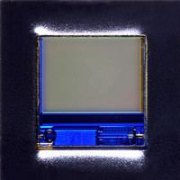
MT9V011P11STC:B Aptina LLC, MT9V011P11STC:B Datasheet - Page 13

MT9V011P11STC:B
Manufacturer Part Number
MT9V011P11STC:B
Description
SENSOR IMAGE VGA COLOR CMOS PLCC
Manufacturer
Aptina LLC
Series
DigitalClarity®, Micron®r
Type
CMOS Imagingr
Datasheets
1.MT9V011P11STCB.pdf
(33 pages)
2.MT9V011P11STCB.pdf
(2 pages)
3.MT9V011P11STCB.pdf
(2 pages)
Specifications of MT9V011P11STC:B
Pixel Size
5.6µm x 5.6µm
Active Pixel Array
640H x 480V
Frames Per Second
30
Voltage - Supply
2.8V
Package / Case
28-PLCC
Lead Free Status / RoHS Status
Lead free / RoHS Compliant
Other names
557-1315
Available stocks
Company
Part Number
Manufacturer
Quantity
Price
Company:
Part Number:
MT9V011P11STC:B
Manufacturer:
RENESAS
Quantity:
1 001
Part Number:
MT9V011P11STC:B
Manufacturer:
MICRON
Quantity:
20 000
Two-wire Serial Interface Sample Read and Write Sequences
16-Bit Write Sequence
Figure 9: Timing Diagram Showing a Write to Reg0x09 with the Value 0x0284
16-Bit Read Sequence
Figure 10: Timing Diagram Showing a Read from Reg0x09; Returned Value 0x0284
PDF: 817d5189/Source: 817d5173
MT9V011_C82S_2_PLCC.fm - Rev. B 1/05 EN
SDATA
SCLK
SDATA
SCLK
START
START
0xBA ADDR
0xBA ADDR
ACK
A typical write sequence for writing 16 bits to a register is shown in Figure 9. A start bit
given by the master, followed by the write address, starts the sequence. The image sen-
sor will then give an acknowledge bit and expects the register address to come first, fol-
lowed by the 16-bit data. After each 8-bit the image sensor will give an acknowledge bit.
All 16 bits must be written before the register will be updated. After 16 bits are trans-
ferred, the register address is automatically incremented, so that the next 16 bits are
written to the next register. The master stops writing by sending a start or stop bit.
A typical read sequence is shown in Figure 10. First the master has to write the register
address, as in a write sequence. Then a start bit and the read address specifies that a read
is about to happen from the register. The master then clocks out the register data eight
bits at a time. The master sends an acknowledge bit after each 8-bit transfer. The register
address is auto-incremented after every 16 bits is transferred. The data transfer is
stopped when the master sends a no-acknowledge bit.
ACK
Reg 0x09
Two-wire Serial Interface Sample Read and Write Sequences
Reg 0x09
ACK
START
0xBB ADDR
MT9V011 - 1/4-Inch VGA Digital Image Sensor
ACK
13
0000 0010
Micron Technology, Inc., reserves the right to change products or specifications without notice.
ACK
0000 0010
ACK
ACK
©2004 Micron Technology, Inc. All rights reserved.
1000 0100
1000 0100
Preliminary
ACK
NACK
STOP
STOP
‡


