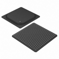
DS33R41+ Maxim Integrated Products, DS33R41+ Datasheet - Page 109

DS33R41+
Manufacturer Part Number
DS33R41+
Description
IC TXRX ETHERNET MAP 400-BGA
Manufacturer
Maxim Integrated Products
Type
Transceiverr
Datasheet
1.DS33R41.pdf
(335 pages)
Specifications of DS33R41+
Number Of Drivers/receivers
4/4
Protocol
T1/E1/J1
Voltage - Supply
3.14 V ~ 3.47 V
Mounting Type
Surface Mount
Package / Case
400-BGA
Lead Free Status / RoHS Status
Lead free / RoHS Compliant
- Current page: 109 of 335
- Download datasheet (2Mb)
DS33R41 Inverse-Multiplexing Ethernet Mapper with Quad Integrated T1/E1/J1 Transceivers
10.25.3 BERT Repetitive Pattern Set
These registers must be properly loaded for the BERT to generate and synchronize to a repetitive pattern, a
pseudorandom pattern, alternating word pattern, or a Daly pattern. For a repetitive pattern that is fewer than 32
bits, the pattern should be repeated so that all 32 bits are used to describe the pattern. For example, if the pattern
was the repeating 5-bit pattern …01101… (where the rightmost bit is the one sent first and received first), then
TR.BRP1 should be loaded with ADh, TR.BRP2 with B5h, TR.BRP3 with D6h, and TR.BRP4 with 5Ah. For a
pseudorandom pattern, all four registers should be loaded with all 1s (i.e., FFh). For an alternating word pattern,
one word should be placed into TR.BRP1 and TR.BRP2 and the other word should be placed into TR.BRP3 and
TR.BRP4. For example, if the DDS stress pattern “7E” is to be described, the user would place 00h in TR.BRP1,
00h in TR.BRP2, 7Eh in TR.BRP3, and 7Eh in TR.BRP4 and the alternating word counter would be set to 50
(decimal) to allow 100 bytes of 00h followed by 100 bytes of 7Eh to be sent and received.
10.25.4 BERT Bit Counter
The BERT Bit Counter is comprised of TR.BBC1, TR.BBC2, TR.BBC3, and TR.BBC4. Once BERT has achieved
synchronization, this 32-bit counter increments for each data bit (i.e., clock) received. Toggling the LC control bit in
TR.BC1 can clear this counter. This counter saturates when full and sets the BBCO status bit.
10.25.5 BERT Error Counter
The BERT Error Counter is comprised of TR.BEC1, TR.BEC2, and TR.BEC3. Once BERT has achieved
synchronization, this 24-bit counter increments for each data bit received in error. Toggling the LC control bit in
TR.BC1 can clear this counter. This counter saturates when full and sets the BECO status bit.
10.25.6 BERT Alternating Word-Count Rate
When the BERT is programmed in the alternating word mode, each word repeats for the count loaded into
TR.BAWC. One word should be placed into TR.BRP1 and TR.BRP2 and the other word should be placed into
TR.BRP3 and TR.BRP4.
109 of 335
Related parts for DS33R41+
Image
Part Number
Description
Manufacturer
Datasheet
Request
R

Part Number:
Description:
MAX7528KCWPMaxim Integrated Products [CMOS Dual 8-Bit Buffered Multiplying DACs]
Manufacturer:
Maxim Integrated Products
Datasheet:

Part Number:
Description:
Single +5V, fully integrated, 1.25Gbps laser diode driver.
Manufacturer:
Maxim Integrated Products
Datasheet:

Part Number:
Description:
Single +5V, fully integrated, 155Mbps laser diode driver.
Manufacturer:
Maxim Integrated Products
Datasheet:

Part Number:
Description:
VRD11/VRD10, K8 Rev F 2/3/4-Phase PWM Controllers with Integrated Dual MOSFET Drivers
Manufacturer:
Maxim Integrated Products
Datasheet:

Part Number:
Description:
Highly Integrated Level 2 SMBus Battery Chargers
Manufacturer:
Maxim Integrated Products
Datasheet:

Part Number:
Description:
Current Monitor and Accumulator with Integrated Sense Resistor; ; Temperature Range: -40°C to +85°C
Manufacturer:
Maxim Integrated Products

Part Number:
Description:
TSSOP 14/A�/RS-485 Transceivers with Integrated 100O/120O Termination Resis
Manufacturer:
Maxim Integrated Products

Part Number:
Description:
TSSOP 14/A�/RS-485 Transceivers with Integrated 100O/120O Termination Resis
Manufacturer:
Maxim Integrated Products

Part Number:
Description:
QFN 16/A�/AC-DC and DC-DC Peak-Current-Mode Converters with Integrated Step
Manufacturer:
Maxim Integrated Products

Part Number:
Description:
TDFN/A/65V, 1A, 600KHZ, SYNCHRONOUS STEP-DOWN REGULATOR WITH INTEGRATED SWI
Manufacturer:
Maxim Integrated Products

Part Number:
Description:
Integrated Temperature Controller f
Manufacturer:
Maxim Integrated Products

Part Number:
Description:
SOT23-6/I�/45MHz to 650MHz, Integrated IF VCOs with Differential Output
Manufacturer:
Maxim Integrated Products

Part Number:
Description:
SOT23-6/I�/45MHz to 650MHz, Integrated IF VCOs with Differential Output
Manufacturer:
Maxim Integrated Products

Part Number:
Description:
EVALUATION KIT/2.4GHZ TO 2.5GHZ 802.11G/B RF TRANSCEIVER WITH INTEGRATED PA
Manufacturer:
Maxim Integrated Products

Part Number:
Description:
QFN/E/DUAL PCIE/SATA HIGH SPEED SWITCH WITH INTEGRATED BIAS RESISTOR
Manufacturer:
Maxim Integrated Products
Datasheet:


