28119 Parallax Inc, 28119 Datasheet - Page 11
28119
Manufacturer Part Number
28119
Description
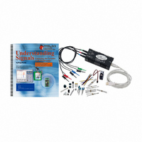
KIT UNDERSTANDING SIGNALS
Manufacturer
Parallax Inc
Datasheet
1.28119.pdf
(137 pages)
Specifications of 28119
Lead Free Status
Contains lead
Accessory Type
Oscilloscope
Interface Type
USB
For Use With/related Products
BASIC Stamp® 2 and Board of Education
Lead Free Status / Rohs Status
Lead free / RoHS Compliant
Available stocks
Company
Part Number
Manufacturer
Quantity
Price
Company:

Part Number:
281197-2
Manufacturer:
TE
Quantity:
20 000
Company:
Part Number:
281197-2
Manufacturer:
MOLEX
Quantity:
2 500


Chapter 1: Oscilloscope Basics · Page 3
The trigger controls when the oscilloscope will start recording the input signal. The
trigger allows you to capture and view only the segment in which you are interested. The
criteria controlling the trigger action is called a trigger event. The OPTAscope 81M has
edge-triggered events. More advanced oscilloscopes have several types of configurable
trigger events: pulse width events, pulse sequence events, and even more exotic event
triggers that can trigger on the start of a video packet in a composite TV signal. This text
will focus on the OPTAscope’s edge-trigger event ability.
There are two types of trigger events supported by the OPTAscope: rising edge, and
falling edge. A rising edge is described as the point at which a relatively low voltage
signal ascends to a relatively higher voltage. The converse is a falling edge. A rising edge
trigger event will occur when the voltage of the signal rises above the set trigger point,
and a falling edge trigger event occurs when the voltage falls below the trigger point.
Upon a valid trigger event, the OPTAscope will begin recording the sampled signal input
and continue until its memory is full.
When the OPTAscope displays the captured signal, the trigger event will be centered in
the display for you to see. A rising edge-triggered signal is depicted in Figure 1-3.
Anything to the left of the trigger event is called “pre-trigger” because it happens before
the trigger event. Anything to the right of the trigger event is called “post trigger”. This is
important because when attempting to trigger the oscilloscope to capture a specific event,
you need to set your trigger level to get as close as possible to the event you want to see.
In Figure 1-3, only one signal is displayed on the screen. With OPTAscope 81M you can
have two signals displayed on the screen at the same time. Both signals are sampled or
recorded concurrently, which allows you to view both signals (called channels) during
the same period of time.
During the exercises in this text, you will use the OPTAscope to trigger, capture, and
display signals. In doing so, you will learn the function and use of oscilloscopes, and gain
a greater understanding of the different signal types you will encounter. Ultimately, you
will also see how these skills can be useful working with different electronics
applications.
Related parts for 28119
Image
Part Number
Description
Manufacturer
Datasheet
Request
R


Part Number:
Description:
Microcontroller Modules & Accessories DISCONTINUED BY PARALLAX
Manufacturer:
Parallax Inc

Part Number:
Description:
BOOK UNDERSTANDING SIGNALS
Manufacturer:
Parallax Inc
Datasheet:


Part Number:
Description:
COMPETITION RING FOR SUMOBOT
Manufacturer:
Parallax Inc
Datasheet:


Part Number:
Description:
TEXT INFRARED REMOTE FOR BOE-BOT
Manufacturer:
Parallax Inc
Datasheet:
Part Number:
Description:
BOARD EXPERIMENT+LCD NX-1000
Manufacturer:
Parallax Inc
Datasheet:

Part Number:
Description:
CONTROLLER 16SERVO MOTOR CONTROL
Manufacturer:
Parallax Inc
Datasheet:

Part Number:
Description:
BASIC STAMP LOGIC ANALYZER
Manufacturer:
Parallax Inc
Datasheet:

Part Number:
Description:
IC MCU 2K FLASH 50MHZ SO-18
Manufacturer:
Parallax Inc
Datasheet: