28119 Parallax Inc, 28119 Datasheet - Page 121
28119
Manufacturer Part Number
28119
Description
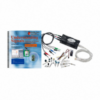
KIT UNDERSTANDING SIGNALS
Manufacturer
Parallax Inc
Datasheet
1.28119.pdf
(137 pages)
Specifications of 28119
Lead Free Status
Contains lead
Accessory Type
Oscilloscope
Interface Type
USB
For Use With/related Products
BASIC Stamp® 2 and Board of Education
Lead Free Status / Rohs Status
Lead free / RoHS Compliant
Available stocks
Company
Part Number
Manufacturer
Quantity
Price
Company:

Part Number:
281197-2
Manufacturer:
TE
Quantity:
20 000
Company:
Part Number:
281197-2
Manufacturer:
MOLEX
Quantity:
2 500


In order to view this signal without a negative supply rail voltage, we can add DC voltage
to move the entire output waveform above 0 V so it will no longer be clipped.
process is called DC offset. This is accomplished with the 10 kΩ potentiometer
connected to the non-inverting input. This means that the op-amp circuit adds a DC
voltage to whatever signal is supplied to the circuit’s inverting input. By twisting the
potentiometer’s knob, the output signal will move into the viewable voltage range.
Parts Required
(1) 20 kΩ resistor
(1) 220 Ω resistor
(1) 10 kΩ resistor
(1) 1.0 µF capacitor
(1) 10 kΩ potentiometer
(1) LM358 op-amp
(9) Jumper Wires
Building the Variable Resistor Op-Amp Circuit
√
Build the circuit shown in Figure 8-14 and Figure 8-15. If you are using the
HomeWork Board, omit the 220 Ω resistor and make the necessary connection
with a jumper wire.
Negative voltages can be viewed by applying a negative 9 V to Vee with a separate power
supply. This is most easily done with a second 9 V battery. Disconnect the op-amp’s Vee
from the Vss on your Board of Education or HomeWork Board. Connect the battery’s
positive terminal to Vss on your Board of Education or HomeWork Board. Then, connect the
battery’s negative terminal to Vee.
WARNING: The 1.0 µF capacitor can explode if it is connected improperly!
Always disconnect the power before building or modifying circuits. Carefully check the
polarity of the 1.0 µF capacitor. The positive terminal (longer leg) must be connected to a
power source pin and the negative terminal (shorter leg) must be connected to Vss (ground).
This
Related parts for 28119
Image
Part Number
Description
Manufacturer
Datasheet
Request
R


Part Number:
Description:
Microcontroller Modules & Accessories DISCONTINUED BY PARALLAX
Manufacturer:
Parallax Inc

Part Number:
Description:
BOOK UNDERSTANDING SIGNALS
Manufacturer:
Parallax Inc
Datasheet:


Part Number:
Description:
COMPETITION RING FOR SUMOBOT
Manufacturer:
Parallax Inc
Datasheet:


Part Number:
Description:
TEXT INFRARED REMOTE FOR BOE-BOT
Manufacturer:
Parallax Inc
Datasheet:
Part Number:
Description:
BOARD EXPERIMENT+LCD NX-1000
Manufacturer:
Parallax Inc
Datasheet:

Part Number:
Description:
CONTROLLER 16SERVO MOTOR CONTROL
Manufacturer:
Parallax Inc
Datasheet:

Part Number:
Description:
BASIC STAMP LOGIC ANALYZER
Manufacturer:
Parallax Inc
Datasheet:

Part Number:
Description:
IC MCU 2K FLASH 50MHZ SO-18
Manufacturer:
Parallax Inc
Datasheet: