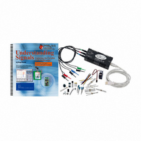
28119 Parallax Inc, 28119 Datasheet - Page 76

28119
Manufacturer Part Number
28119
Description
KIT UNDERSTANDING SIGNALS
Manufacturer
Parallax Inc
Datasheet
1.28119.pdf
(137 pages)
Specifications of 28119
Lead Free Status
Contains lead
Accessory Type
Oscilloscope
Interface Type
USB
For Use With/related Products
BASIC Stamp® 2 and Board of Education
Lead Free Status / Rohs Status
Lead free / RoHS Compliant
Available stocks
Company
Part Number
Manufacturer
Quantity
Price
Company:
Part Number:
281197-2
Manufacturer:
TE
Quantity:
20 000
Company:
Part Number:
281197-2
Manufacturer:
MOLEX
Quantity:
2 500
- Current page: 76 of 137
- Download datasheet (5Mb)
' -----[ Subroutines ]-----------------------------------------------------
ADC_Data:
RETURN
Display:
RETURN
The blue signal at the bottom is the data signal. The data signal is what communicates a
“1” or “0” to the device you are trying to talk to. A “1” is detected when the signal is
above the TTL threshold, a “0” when the signal is below the TTL threshold.
The red signal on top is the clock. The clock tells the device you are talking to when to
sample the data signal. This happens on the rising edge of the clock signal. At that instant
in time the receiving device will look at the data line and latch in that value, a “1” or a
“0”. That explains why this is synchronous serial communication; the master (the BASIC
Stamp) and the slave (the ADC0831) agree to send and receive data according to the state
of a second signal, the clock.
HIGH CS
LOW CS
LOW CLK
PULSOUT CLK, 210
SHIFTIN DataOutput,CLK,MSBPOST,[adcBits\8]
DEBUG HOME
DEBUG "8-bit binary value:
DEBUG CR, CR, "Decimal Value: ", DEC3 adcBits
√
√
√
√
Use the red and blue arrows to separate the two signals in the display, as shown
in Figure 5-5.
Next, put your BASIC Stamp Debug Terminal side by side with your
OPTAscope display to see the values you are receiving from the OPTAscope.
Adjust the potentiometer tap by gently twisting the knob until the Debug
Terminal Decimal Value reads 080. Your signals should now look like those in
Figure 5-5.
If you do not get a similar signal, make sure your Trigger Mode switch is set to
Normal. Also, you may need to slide your Plot Area Indicator bar to the right to find
the whole signal.
Clock Line vs. Data Line: The BASIC Stamp controls the clock line, but it is the ADC0831
that controls the data line
", BIN8 adcBits
Related parts for 28119
Image
Part Number
Description
Manufacturer
Datasheet
Request
R

Part Number:
Description:
Microcontroller Modules & Accessories DISCONTINUED BY PARALLAX
Manufacturer:
Parallax Inc

Part Number:
Description:
BOOK UNDERSTANDING SIGNALS
Manufacturer:
Parallax Inc
Datasheet:

Part Number:
Description:
COMPETITION RING FOR SUMOBOT
Manufacturer:
Parallax Inc
Datasheet:

Part Number:
Description:
TEXT INFRARED REMOTE FOR BOE-BOT
Manufacturer:
Parallax Inc
Datasheet:

Part Number:
Description:
BOARD EXPERIMENT+LCD NX-1000
Manufacturer:
Parallax Inc
Datasheet:

Part Number:
Description:
CONTROLLER 16SERVO MOTOR CONTROL
Manufacturer:
Parallax Inc
Datasheet:

Part Number:
Description:
BASIC STAMP LOGIC ANALYZER
Manufacturer:
Parallax Inc
Datasheet:

Part Number:
Description:
IC MCU 2K FLASH 50MHZ SO-18
Manufacturer:
Parallax Inc
Datasheet:


