28119 Parallax Inc, 28119 Datasheet - Page 112
28119
Manufacturer Part Number
28119
Description
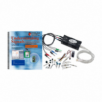
KIT UNDERSTANDING SIGNALS
Manufacturer
Parallax Inc
Datasheet
1.28119.pdf
(137 pages)
Specifications of 28119
Lead Free Status
Contains lead
Accessory Type
Oscilloscope
Interface Type
USB
For Use With/related Products
BASIC Stamp® 2 and Board of Education
Lead Free Status / Rohs Status
Lead free / RoHS Compliant
Available stocks
Company
Part Number
Manufacturer
Quantity
Price
Company:

Part Number:
281197-2
Manufacturer:
TE
Quantity:
20 000
Company:
Part Number:
281197-2
Manufacturer:
MOLEX
Quantity:
2 500


Therefore, a 20 kΩ resistor is needed for Rf, given a 10 kΩ resistor for Ri and a desired
gain of 2. Remember, the 10 kΩ resistor in the input impedance of the op-amp.
Two 10 kΩ resistors would present themselves as an additional load (Figure 8-6). The
two 10 kΩ resistors when measured at the middle should yield 2.5 V. When you connect
your op-amp circuit to a 2.5 V signal, you might see something less than 2.5 V. The
output impedance of the resistor divider is high, meaning it does not supply very much
current. The inverting op-amp circuit has low input impedance, hence the 10 kΩ input
resistor. So, the op-amp circuit will load down the 2.5 V signal, causing it to sag.
When using inverting op-amp circuits, keep what you have just learned in mind. You can
increase the value of Ri in the op-amp circuit to increase the input impedance, but if you
can, keep the value around 10 kΩ.
A non-inverting voltage amplifier has its input signal applied directly to the non-inverting
input of the op-amp (Figure 8-7). This gives you very high input impedance, up to 2 MΩ
Vss
Vss
+5
Signal
Ri
Vss
Vss
OPAMP 10 k Input
approximation
impedance
Rf
Vss
Vout
Figure 8-6:
Two 10k resistors
have significant
output impedance.
Figure 8-7:
Non-inverting
Voltage Amplifier
Related parts for 28119
Image
Part Number
Description
Manufacturer
Datasheet
Request
R


Part Number:
Description:
Microcontroller Modules & Accessories DISCONTINUED BY PARALLAX
Manufacturer:
Parallax Inc

Part Number:
Description:
BOOK UNDERSTANDING SIGNALS
Manufacturer:
Parallax Inc
Datasheet:


Part Number:
Description:
COMPETITION RING FOR SUMOBOT
Manufacturer:
Parallax Inc
Datasheet:


Part Number:
Description:
TEXT INFRARED REMOTE FOR BOE-BOT
Manufacturer:
Parallax Inc
Datasheet:
Part Number:
Description:
BOARD EXPERIMENT+LCD NX-1000
Manufacturer:
Parallax Inc
Datasheet:

Part Number:
Description:
CONTROLLER 16SERVO MOTOR CONTROL
Manufacturer:
Parallax Inc
Datasheet:

Part Number:
Description:
BASIC STAMP LOGIC ANALYZER
Manufacturer:
Parallax Inc
Datasheet:

Part Number:
Description:
IC MCU 2K FLASH 50MHZ SO-18
Manufacturer:
Parallax Inc
Datasheet: