28119 Parallax Inc, 28119 Datasheet - Page 32
28119
Manufacturer Part Number
28119
Description
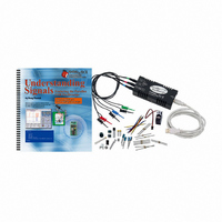
KIT UNDERSTANDING SIGNALS
Manufacturer
Parallax Inc
Datasheet
1.28119.pdf
(137 pages)
Specifications of 28119
Lead Free Status
Contains lead
Accessory Type
Oscilloscope
Interface Type
USB
For Use With/related Products
BASIC Stamp® 2 and Board of Education
Lead Free Status / Rohs Status
Lead free / RoHS Compliant
Available stocks
Company
Part Number
Manufacturer
Quantity
Price
Company:

Part Number:
281197-2
Manufacturer:
TE
Quantity:
20 000
Company:
Part Number:
281197-2
Manufacturer:
MOLEX
Quantity:
2 500


The
The
and the second argument, 750, is a variable or constant (0 – 65,535) that specifies the
duration of the pulse in 2 µs increments. A pulse of 1.5 ms sent every 20 ms positions the
servo in its centered location. Here is how this is calculated:
or
Now that we know the value for the
program the BASIC Stamp. With an output pulse of 1.5 ms, the expected result from the
servo is that it centers itself and stays put.
1.5
PulseWidth
2
PULSOUT
PULSOUT
×
PULSOUT 5, 750
1,000
Servo power supply voltage is critical; applying more than ~6.5 VDC to servos will
permanently damage them.
rather than the schematics and a 9 V battery in the following Activity, please note:
The Board of Education Rev B has four servo ports (P12-P15) appearing in a terminal block
header on the right side of the board. The power supply for these ports is connected directly
to Vin (the input voltage). If you are using a wall pack (anything more than +6 V) don’t plug
the servos into the terminal block – you’ll put 9-15 V on the servos and they’ll be destroyed.
The terminal block is strictly for battery powered applications where the battery voltage is 6
VDC.
The Board of Education Rev C has a jumper selector that allows the user to select Vin or
Vdd for the servo supply power. Consider your power supply and position this jumper
appropriately if you choose to use the servo ports.
If you wish to use a higher input supply voltage, use the +5 V (Vdd) power supply above the
breadboard, and plug the servos into the breadboard using the 3-pin male/male header pins.
This will save many headaches and time lost destroying servos.
2
command is used in the following activities. It has this format:
command’s first argument, 5, states the BASIC Stamp I/O pin to be used,
=
(ms)
750
×
1,000
=
Variable
PULSOUT
If you wish to use the Board of Education Servo ports
' 1.5 ms pulse on P5
command, we can build the experiment and
Related parts for 28119
Image
Part Number
Description
Manufacturer
Datasheet
Request
R


Part Number:
Description:
Microcontroller Modules & Accessories DISCONTINUED BY PARALLAX
Manufacturer:
Parallax Inc

Part Number:
Description:
BOOK UNDERSTANDING SIGNALS
Manufacturer:
Parallax Inc
Datasheet:


Part Number:
Description:
COMPETITION RING FOR SUMOBOT
Manufacturer:
Parallax Inc
Datasheet:


Part Number:
Description:
TEXT INFRARED REMOTE FOR BOE-BOT
Manufacturer:
Parallax Inc
Datasheet:
Part Number:
Description:
BOARD EXPERIMENT+LCD NX-1000
Manufacturer:
Parallax Inc
Datasheet:

Part Number:
Description:
CONTROLLER 16SERVO MOTOR CONTROL
Manufacturer:
Parallax Inc
Datasheet:

Part Number:
Description:
BASIC STAMP LOGIC ANALYZER
Manufacturer:
Parallax Inc
Datasheet:

Part Number:
Description:
IC MCU 2K FLASH 50MHZ SO-18
Manufacturer:
Parallax Inc
Datasheet: