28119 Parallax Inc, 28119 Datasheet - Page 91
28119
Manufacturer Part Number
28119
Description
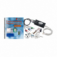
KIT UNDERSTANDING SIGNALS
Manufacturer
Parallax Inc
Datasheet
1.28119.pdf
(137 pages)
Specifications of 28119
Lead Free Status
Contains lead
Accessory Type
Oscilloscope
Interface Type
USB
For Use With/related Products
BASIC Stamp® 2 and Board of Education
Lead Free Status / Rohs Status
Lead free / RoHS Compliant
Available stocks
Company
Part Number
Manufacturer
Quantity
Price
Company:

Part Number:
281197-2
Manufacturer:
TE
Quantity:
20 000
Company:
Part Number:
281197-2
Manufacturer:
MOLEX
Quantity:
2 500


Building the Infrared Object Detection Circuit
To make this circuit work properly, the infrared LED and detector should both point
forward.
√
√
√
√
P8
P7
Build the circuit shown in Figure 7-3 and Figure 7-4. If you are using a BASIC
Stamp HomeWork Board omit the 220 Ω resistor and make the necessary
connection with a jumper wire.
Connect the CH1 probe to the jumper wire between the LED and resistor.
Connect the CH2 probe to the jumper wire at the junction of P8 and the infrared
receiver.
Connect Ground probe to the jumper wire in Vss.
Infrared LED Assembly: Your infrared LED should be assembled before using it in a
circuit. There are three parts: the IR LED (emitter), the LED Standoff (large cylinder) and
the LED Light Shield (small cylinder).
1.
2.
Insert the IR LED into the Standoff so that its pins come through the small holes in the
bottom. The IR LED should snap into place.
Snap the Light Shield onto the end of the Standoff over the IR LED.
220
Ω
LED
Vdd
Vss
OPTA
OPTA
OPTA
scope
scope
scope
CH2
CH1
GND
Figure 7-3:
Infrared object
detection circuit
schematic.
Note: If you are using
the BASIC Stamp
HomeWork Board
leave the 220 Ω
resistor out of the
circuit – it is already
installed between the
I/O pin and the
connection header.
Related parts for 28119
Image
Part Number
Description
Manufacturer
Datasheet
Request
R


Part Number:
Description:
Microcontroller Modules & Accessories DISCONTINUED BY PARALLAX
Manufacturer:
Parallax Inc

Part Number:
Description:
BOOK UNDERSTANDING SIGNALS
Manufacturer:
Parallax Inc
Datasheet:


Part Number:
Description:
COMPETITION RING FOR SUMOBOT
Manufacturer:
Parallax Inc
Datasheet:


Part Number:
Description:
TEXT INFRARED REMOTE FOR BOE-BOT
Manufacturer:
Parallax Inc
Datasheet:
Part Number:
Description:
BOARD EXPERIMENT+LCD NX-1000
Manufacturer:
Parallax Inc
Datasheet:

Part Number:
Description:
CONTROLLER 16SERVO MOTOR CONTROL
Manufacturer:
Parallax Inc
Datasheet:

Part Number:
Description:
BASIC STAMP LOGIC ANALYZER
Manufacturer:
Parallax Inc
Datasheet:

Part Number:
Description:
IC MCU 2K FLASH 50MHZ SO-18
Manufacturer:
Parallax Inc
Datasheet: