28119 Parallax Inc, 28119 Datasheet - Page 110
28119
Manufacturer Part Number
28119
Description
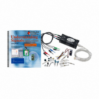
KIT UNDERSTANDING SIGNALS
Manufacturer
Parallax Inc
Datasheet
1.28119.pdf
(137 pages)
Specifications of 28119
Lead Free Status
Contains lead
Accessory Type
Oscilloscope
Interface Type
USB
For Use With/related Products
BASIC Stamp® 2 and Board of Education
Lead Free Status / Rohs Status
Lead free / RoHS Compliant
Available stocks
Company
Part Number
Manufacturer
Quantity
Price
Company:

Part Number:
281197-2
Manufacturer:
TE
Quantity:
20 000
Company:
Part Number:
281197-2
Manufacturer:
MOLEX
Quantity:
2 500


AN OP-AMP USED AS A BUFFER
Sometimes, when connecting two circuits that were designed to each perform a specific
function, the connection allows an interaction that makes the new combined circuit
behave in unwanted ways. To prevent this unwanted interaction, a buffer circuit can be
inserted between the two circuits, connecting them yet allowing them to operate as
originally intended. Op-amps are commonly used to quickly and easily fashion buffers,
which isolate and buffer circuits in a larger network. An example of an op-amp buffer
circuit is shown in Figure 8-4.
Functionally, a buffer circuit aims to generate an output that is identical to the input it
receives. To use an op-amp as a buffer, make sure you have proper supply voltages
(discussed below) and a fast enough slew rate. For all BASIC stamp applications, the
LM358 has fast enough slew rate for the job.
For example, let’s say we want to buffer a signal out of the BASIC Stamp that swings
from 0 V to 5 V. To prevent the LM358 from clipping the output, Vcc should be
supplied with a voltage that is 1.5 V higher than 5 V to prevent the signal from clipping.
Also, the power supply may fluctuate, so to be on the safe side, increase Vcc by another
10-20% (depending on the precision of your power supply).
Likewise, the supply voltage at Vee needs to be 20 mV below the lowest possible voltage
value of the input signal. Since the input signal is expected to drop as low as 0 V, the
Vee supply must be at least -20 mV. Again, you may also want to adjust downward by
another 10-20% in anticipation of power supply fluctuation.
Signal
Vss
Vcc
Vee
Vss
Vout
Figure 8-4:
An op-amp used
as a buffer
Related parts for 28119
Image
Part Number
Description
Manufacturer
Datasheet
Request
R


Part Number:
Description:
Microcontroller Modules & Accessories DISCONTINUED BY PARALLAX
Manufacturer:
Parallax Inc

Part Number:
Description:
BOOK UNDERSTANDING SIGNALS
Manufacturer:
Parallax Inc
Datasheet:


Part Number:
Description:
COMPETITION RING FOR SUMOBOT
Manufacturer:
Parallax Inc
Datasheet:


Part Number:
Description:
TEXT INFRARED REMOTE FOR BOE-BOT
Manufacturer:
Parallax Inc
Datasheet:
Part Number:
Description:
BOARD EXPERIMENT+LCD NX-1000
Manufacturer:
Parallax Inc
Datasheet:

Part Number:
Description:
CONTROLLER 16SERVO MOTOR CONTROL
Manufacturer:
Parallax Inc
Datasheet:

Part Number:
Description:
BASIC STAMP LOGIC ANALYZER
Manufacturer:
Parallax Inc
Datasheet:

Part Number:
Description:
IC MCU 2K FLASH 50MHZ SO-18
Manufacturer:
Parallax Inc
Datasheet: