28119 Parallax Inc, 28119 Datasheet - Page 77
28119
Manufacturer Part Number
28119
Description
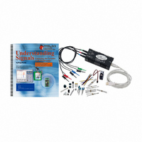
KIT UNDERSTANDING SIGNALS
Manufacturer
Parallax Inc
Datasheet
1.28119.pdf
(137 pages)
Specifications of 28119
Lead Free Status
Contains lead
Accessory Type
Oscilloscope
Interface Type
USB
For Use With/related Products
BASIC Stamp® 2 and Board of Education
Lead Free Status / Rohs Status
Lead free / RoHS Compliant
Available stocks
Company
Part Number
Manufacturer
Quantity
Price
Company:

Part Number:
281197-2
Manufacturer:
TE
Quantity:
20 000
Company:
Part Number:
281197-2
Manufacturer:
MOLEX
Quantity:
2 500


The lines in Figure 5-4 indicate the rising edge of the clock. Where that line meets the
data signal is the value of the data signal that will be received by the BASIC Stamp.
Let’s take a look at the BASIC Stamp command that generates this signal:
The first two arguments set what pins the clock and data signals will be assigned to. The
next sets the data format.
that the first value received will be placed in the most significant bit of the
variable. The
pulse. The next argument specifies the variable to receive the data.
√
√
Compare the data signal from Channel 1 to the 8-bit binary value for number 80
as shown in the Debug Terminal. Can you recognize the binary number in signal
form?
Gently adjust the potentiometer tap knob to view other decimal values, and
compare their binary forms to the data signal.
SHIFTIN DataOutput,CLK,MSBPOST,[adcBits\8]
POST
potion tells the BASIC Stamp to check for that value after the clock
MSBPOST
specifies tow things. First, the
MSB
portion means
Figure 5-4:
Clock line
and data line
Where the
clock line
meets the
data signal is
the value of
the data
signal that
will get
clocked into
the BASIC
Stamp
adcBits
Related parts for 28119
Image
Part Number
Description
Manufacturer
Datasheet
Request
R


Part Number:
Description:
Microcontroller Modules & Accessories DISCONTINUED BY PARALLAX
Manufacturer:
Parallax Inc

Part Number:
Description:
BOOK UNDERSTANDING SIGNALS
Manufacturer:
Parallax Inc
Datasheet:


Part Number:
Description:
COMPETITION RING FOR SUMOBOT
Manufacturer:
Parallax Inc
Datasheet:


Part Number:
Description:
TEXT INFRARED REMOTE FOR BOE-BOT
Manufacturer:
Parallax Inc
Datasheet:
Part Number:
Description:
BOARD EXPERIMENT+LCD NX-1000
Manufacturer:
Parallax Inc
Datasheet:

Part Number:
Description:
CONTROLLER 16SERVO MOTOR CONTROL
Manufacturer:
Parallax Inc
Datasheet:

Part Number:
Description:
BASIC STAMP LOGIC ANALYZER
Manufacturer:
Parallax Inc
Datasheet:

Part Number:
Description:
IC MCU 2K FLASH 50MHZ SO-18
Manufacturer:
Parallax Inc
Datasheet: