C8051F540-TB Silicon Laboratories Inc, C8051F540-TB Datasheet - Page 260
C8051F540-TB
Manufacturer Part Number
C8051F540-TB
Description
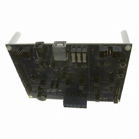
BOARD PROTOTYPE W/C8051F540
Manufacturer
Silicon Laboratories Inc
Type
MCUr
Specifications of C8051F540-TB
Contents
Board
Processor To Be Evaluated
C8051F54x
Processor Series
C8051F54x
Interface Type
USB
Operating Supply Voltage
5 V
Lead Free Status / RoHS Status
Lead free / RoHS Compliant
For Use With/related Products
C8051F54x
Lead Free Status / Rohs Status
Lead free / RoHS Compliant
Other names
336-1672


C8051F54x
24.4. Watchdog Timer Mode
A programmable watchdog timer (WDT) function is available through the PCA Module 5. The WDT is used
to generate a reset if the time between writes to the WDT update register (PCA0CPH5) exceed a specified
limit. The WDT can be configured and enabled/disabled as needed by software.
With the WDTE bit set in the PCA0MD register, Module 5 operates as a watchdog timer (WDT). The Mod-
ule 5 high byte is compared to the PCA counter high byte; the Module 5 low byte holds the offset to be
used when WDT updates are performed. The Watchdog Timer is enabled on reset. Writes to some
PCA registers are restricted while the Watchdog Timer is enabled. The WDT will generate a reset
shortly after code begins execution. To avoid this reset, the WDT should be explicitly disabled (and option-
ally re-configured and re-enabled if it is used in the system).
24.4.1. Watchdog Timer Operation
While the WDT is enabled:
While the WDT is enabled, writes to the CR bit will not change the PCA counter state; the counter will run
until the WDT is disabled. The PCA counter run control bit (CR) will read zero if the WDT is enabled but
user software has not enabled the PCA counter. If a match occurs between PCA0CPH5 and PCA0H while
the WDT is enabled, a reset will be generated. To prevent a WDT reset, the WDT may be updated with a
write of any value to PCA0CPH5. Upon a PCA0CPH5 write, PCA0H plus the offset held in PCA0CPL5 is
loaded into PCA0CPH5 (See Figure 24.11).
260
PCA0CPLn
PCA counter is forced on.
Writes to PCA0L and PCA0H are not allowed.
PCA clock source bits (CPS[2:0]) are frozen.
PCA Idle control bit (CIDL) is frozen.
Module 5 is forced into software timer mode.
Writes to the Module 5 mode register (PCA0CPM5) are disabled.
Write to
Reset
PCA0CPHn
Write to
0
1
ENB
ENB
W
P
M
1
6
n
1
O
M
E
C
n
PCA0CPMn
C
A
P
P
n
0 0 x 0
C
A
P
N
n
M
A
T
n
PCA Timebase
O
G
T
n
W
P
M
n
E
C
C
F
n
x
Figure 24.10. PCA 16-Bit PWM Mode
Enable
PCA0CPHn
PCA0H
16-bit Comparator
Rev. 1.1
PCA0CPLn
PCA0L
Overflow
match
S
R
SET
CLR
Q
Q
CEXn
Crossbar
Port I/O
Related parts for C8051F540-TB
Image
Part Number
Description
Manufacturer
Datasheet
Request
R

Part Number:
Description:
SMD/C°/SINGLE-ENDED OUTPUT SILICON OSCILLATOR
Manufacturer:
Silicon Laboratories Inc
Part Number:
Description:
Manufacturer:
Silicon Laboratories Inc
Datasheet:
Part Number:
Description:
N/A N/A/SI4010 AES KEYFOB DEMO WITH LCD RX
Manufacturer:
Silicon Laboratories Inc
Datasheet:
Part Number:
Description:
N/A N/A/SI4010 SIMPLIFIED KEY FOB DEMO WITH LED RX
Manufacturer:
Silicon Laboratories Inc
Datasheet:
Part Number:
Description:
N/A/-40 TO 85 OC/EZLINK MODULE; F930/4432 HIGH BAND (REV E/B1)
Manufacturer:
Silicon Laboratories Inc
Part Number:
Description:
EZLink Module; F930/4432 Low Band (rev e/B1)
Manufacturer:
Silicon Laboratories Inc
Part Number:
Description:
I°/4460 10 DBM RADIO TEST CARD 434 MHZ
Manufacturer:
Silicon Laboratories Inc
Part Number:
Description:
I°/4461 14 DBM RADIO TEST CARD 868 MHZ
Manufacturer:
Silicon Laboratories Inc
Part Number:
Description:
I°/4463 20 DBM RFSWITCH RADIO TEST CARD 460 MHZ
Manufacturer:
Silicon Laboratories Inc
Part Number:
Description:
I°/4463 20 DBM RADIO TEST CARD 868 MHZ
Manufacturer:
Silicon Laboratories Inc
Part Number:
Description:
I°/4463 27 DBM RADIO TEST CARD 868 MHZ
Manufacturer:
Silicon Laboratories Inc
Part Number:
Description:
I°/4463 SKYWORKS 30 DBM RADIO TEST CARD 915 MHZ
Manufacturer:
Silicon Laboratories Inc
Part Number:
Description:
N/A N/A/-40 TO 85 OC/4463 RFMD 30 DBM RADIO TEST CARD 915 MHZ
Manufacturer:
Silicon Laboratories Inc
Part Number:
Description:
I°/4463 20 DBM RADIO TEST CARD 169 MHZ
Manufacturer:
Silicon Laboratories Inc