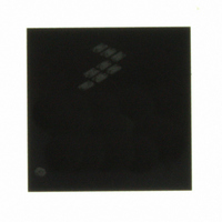
MC9S08AC60CFDE Freescale Semiconductor, MC9S08AC60CFDE Datasheet - Page 319

MC9S08AC60CFDE
Manufacturer Part Number
MC9S08AC60CFDE
Description
IC MCU 8BIT 60K FLASH 48-QFN
Manufacturer
Freescale Semiconductor
Series
HCS08r
Datasheet
1.MC9S08AC60CFJE.pdf
(348 pages)
Specifications of MC9S08AC60CFDE
Core Processor
HCS08
Core Size
8-Bit
Speed
40MHz
Connectivity
I²C, SCI, SPI
Peripherals
LVD, POR, PWM, WDT
Number Of I /o
38
Program Memory Size
60KB (60K x 8)
Program Memory Type
FLASH
Ram Size
2K x 8
Voltage - Supply (vcc/vdd)
2.7 V ~ 5.5 V
Data Converters
A/D 8x10b
Oscillator Type
Internal
Operating Temperature
-40°C ~ 85°C
Package / Case
48-QFN
Processor Series
S08AC
Core
HCS08
Data Bus Width
8 bit
Data Ram Size
2 KB
Interface Type
I2C/SCI/SPI
Maximum Clock Frequency
40 MHz
Number Of Programmable I/os
56
Number Of Timers
3
Maximum Operating Temperature
+ 85 C
Mounting Style
SMD/SMT
3rd Party Development Tools
EWS08
Development Tools By Supplier
DEMO9S08AC60E, DEMOACEX, DEMOACKIT, DCF51AC256, DC9S08AC128, DC9S08AC16, DC9S08AC60, DEMO51AC256KIT
Minimum Operating Temperature
- 40 C
On-chip Adc
16-ch x 10-bit
Controller Family/series
HCS08
No. Of I/o's
38
Ram Memory Size
2KB
Cpu Speed
40MHz
No. Of Timers
3
Rohs Compliant
Yes
Height
1 mm
Length
7 mm
Supply Voltage (max)
5.5 V, 5.5 V
Supply Voltage (min)
2.7 V, 2.7 V
Width
7 mm
For Use With
DEMO9S08AC60E - BOARD DEMO FOR MC9S08A
Lead Free Status / RoHS Status
Lead free / RoHS Compliant
Eeprom Size
-
Lead Free Status / Rohs Status
Lead free / RoHS Compliant
- Current page: 319 of 348
- Download datasheet (4Mb)
3
4
5
6
7
8
9
Freescale Semiconductor
Loss of reference frequency is the reference frequency detected internally, which transitions the ICG into self-clocked mode if it
is not in the desired range.
Loss of DCO frequency is the DCO frequency detected internally, which transitions the ICG into FLL bypassed external mode
(if an external reference exists) if it is not in the desired range.
This parameter is characterized before qualification rather than 100% tested.
Proper PC board layout procedures must be followed to achieve specifications.
This specification applies to the period of time required for the FLL to lock after entering FLL engaged internal or external modes.
If a crystal/resonator is being used as the reference, this specification assumes it is already running.
Jitter is the average deviation from the programmed frequency measured over the specified interval at maximum f
Measurements are made with the device powered by filtered supplies and clocked by a stable external clock signal. Noise
injected into the FLL circuitry via V
a given interval.
See
Figure
A-9.
Average of Percentage Error
Figure A-9. Internal Oscillator Deviation from Trimmed Frequency
DDA
and V
MC9S08AC60 Series Data Sheet, Rev. 2
SSA
and variation in crystal oscillator frequency increase the C
Appendix A Electrical Characteristics and Timing Specifications
Variable
3 V
5 V
Jitter
percentage for
ICGOUT
.
319
Related parts for MC9S08AC60CFDE
Image
Part Number
Description
Manufacturer
Datasheet
Request
R
Part Number:
Description:
Manufacturer:
Freescale Semiconductor, Inc
Datasheet:
Part Number:
Description:
Manufacturer:
Freescale Semiconductor, Inc
Datasheet:
Part Number:
Description:
Manufacturer:
Freescale Semiconductor, Inc
Datasheet:
Part Number:
Description:
Manufacturer:
Freescale Semiconductor, Inc
Datasheet:
Part Number:
Description:
Manufacturer:
Freescale Semiconductor, Inc
Datasheet:
Part Number:
Description:
Manufacturer:
Freescale Semiconductor, Inc
Datasheet:
Part Number:
Description:
Manufacturer:
Freescale Semiconductor, Inc
Datasheet:
Part Number:
Description:
Manufacturer:
Freescale Semiconductor, Inc
Datasheet:
Part Number:
Description:
Manufacturer:
Freescale Semiconductor, Inc
Datasheet:
Part Number:
Description:
Manufacturer:
Freescale Semiconductor, Inc
Datasheet:
Part Number:
Description:
Manufacturer:
Freescale Semiconductor, Inc
Datasheet:
Part Number:
Description:
Manufacturer:
Freescale Semiconductor, Inc
Datasheet:
Part Number:
Description:
Manufacturer:
Freescale Semiconductor, Inc
Datasheet:
Part Number:
Description:
Manufacturer:
Freescale Semiconductor, Inc
Datasheet:
Part Number:
Description:
Manufacturer:
Freescale Semiconductor, Inc
Datasheet:


