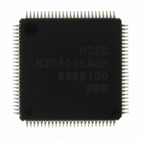
M30800SAGP#U5 Renesas Electronics America, M30800SAGP#U5 Datasheet - Page 143

M30800SAGP#U5
Manufacturer Part Number
M30800SAGP#U5
Description
IC M32C/80 MCU ROMLESS 100LQFP
Manufacturer
Renesas Electronics America
Series
M16C™ M32C/80r
Datasheet
1.M30800SAGP-BLU5.pdf
(354 pages)
Specifications of M30800SAGP#U5
Core Processor
M16C/80
Core Size
16-Bit
Speed
20MHz
Connectivity
I²C, IEBus, SIO, UART/USART
Peripherals
DMA, WDT
Number Of I /o
45
Program Memory Type
ROMless
Ram Size
8K x 8
Voltage - Supply (vcc/vdd)
3 V ~ 5.5 V
Data Converters
A/D 10x10b, D/A 2x8b
Oscillator Type
Internal
Operating Temperature
-20°C ~ 85°C
Package / Case
100-LQFP
For Use With
R0K330879S001BE - KIT DEV RSK M32C/87R0K330879S000BE - KIT DEV RSK M32C/87
Lead Free Status / RoHS Status
Lead free / RoHS Compliant
Eeprom Size
-
Program Memory Size
-
Available stocks
Company
Part Number
Manufacturer
Quantity
Price
Part Number:
M30800SAGP#U5M30800SAGP#D3
Manufacturer:
Renesas Electronics America
Quantity:
10 000
- Current page: 143 of 354
- Download datasheet (3Mb)
R
R
M
e
E
3
. v
J
2
Figure 13.2 DMAC II Index
0
C
13.1.2 DMAC II Index
1
9
0 .
8 /
B
transfer function is selected). The DMAC II index stores parameters for transfer mode, transfer counter,
source address (or immediate data), operation address as an address to be calculated, destination ad-
dress, chained transfer address, and end-of-transfer interrupt address.
This DMAC II index must be located on the RAM area.
Figure 13.2 shows a configuration of the DMAC II index. Table 13.2 lists a configuration of the DMAC II
index in transfer mode.
The followings are details of the DMAC II index. Set these parameters in the specified order listed in
Table 13.2, according to DMAC II transfer mode.
The DMAC II index is a data table which comprises 8 to 18 bytes (maximum 32 bytes when the multiple
0
0
• Transfer mode (MOD)
• Transfer counter (COUNT)
• Transfer source address (SADR)
• Operation address (OADR)
• Transfer destination address (DADR)
• Chained transfer address (CADR)
• End-of-transfer interrupt address (IADR)
0
2
DMAC II Index
Starting Address
(BASE)
7
G
N
1
the calculation transfer function.
this data only when using the chained transfer function.
data only when using the end-of-transfer interrupt.
Two-byte data is required to set transfer mode. Figure 13.3 shows a configuration for transfer mode.
Two-byte data is required to set the number of transfer.
Two-byte data is required to set the source memory address or immediate data.
Two-byte data is required to set a memory address to be calculated. Set this data only when using
Two-byte data is required to set the destination memory address.
Four-byte data is required to set the starting address of the DMAC II index for the next transfer. Set
Four-byte data is required to set a jump address for end-of-transfer interrupt processing. Set this
o
The DMAC II index must be located on the RAM. Necessary data is set front-aligned. For example, if not using a calculation
transfer function, set destination address to BASE+6. (See Table 13.2)
Starting address of the DMAC II index must be set in the interrupt vector for the peripheral function interrupt causing a DMAC II request.
o r
0 -
. v
u
1
BASE + 2
BASE + 4
BASE + 6
BASE + 8
BASE + 10
BASE + 12
BASE + 14
BASE + 16
0
0
p
, 1
0
NOTES:
Memory-to-Memory Transfer, Immediate Transfer,
Calculation Transfer
2
1. This data is not required when not using the calculation transfer function.
2. This data is not required when not using the chained transfer function.
3. This data is not required when not using the end-of-transfer interrupt.
0
0
5
Transfer Counter
Transfer Source Address (or immediate data) (SADR)
Operation Address
Transfer Destination Address
Chained Transfer Address
Chained Transfer Address
End-of-Transfer Interrupt Address
End-of-Transfer Interrupt Address
Page 122
Transfer Mode
f o
3
(1)
3
16 bits
0
(2)
(2)
(3)
(3)
(COUNT)
(OADR)
(DADR)
(CADR0)
(CADR1)
(IADR0)
(IADR1)
(MOD)
BASE
BASE + 2
BASE + 4
BASE + 6
BASE + 8
BASE + 10
BASE + 28
BASE + 30
Multiple Transfer
Transfer Counter
Transfer Source Address
Transfer Destination Address
Transfer Source Address
Transfer Destination Address
Transfer Source Address
Transfer Destination Address
Transfer Mode
16 bits
(COUNT)
(SADR1)
(DADR1)
(SADR2)
(DADR2)
(SADR7)
(DADR7)
(MOD)
13. DMACII
Related parts for M30800SAGP#U5
Image
Part Number
Description
Manufacturer
Datasheet
Request
R

Part Number:
Description:
KIT STARTER FOR M16C/29
Manufacturer:
Renesas Electronics America
Datasheet:

Part Number:
Description:
KIT STARTER FOR R8C/2D
Manufacturer:
Renesas Electronics America
Datasheet:

Part Number:
Description:
R0K33062P STARTER KIT
Manufacturer:
Renesas Electronics America
Datasheet:

Part Number:
Description:
KIT STARTER FOR R8C/23 E8A
Manufacturer:
Renesas Electronics America
Datasheet:

Part Number:
Description:
KIT STARTER FOR R8C/25
Manufacturer:
Renesas Electronics America
Datasheet:

Part Number:
Description:
KIT STARTER H8S2456 SHARPE DSPLY
Manufacturer:
Renesas Electronics America
Datasheet:

Part Number:
Description:
KIT STARTER FOR R8C38C
Manufacturer:
Renesas Electronics America
Datasheet:

Part Number:
Description:
KIT STARTER FOR R8C35C
Manufacturer:
Renesas Electronics America
Datasheet:

Part Number:
Description:
KIT STARTER FOR R8CL3AC+LCD APPS
Manufacturer:
Renesas Electronics America
Datasheet:

Part Number:
Description:
KIT STARTER FOR RX610
Manufacturer:
Renesas Electronics America
Datasheet:

Part Number:
Description:
KIT STARTER FOR R32C/118
Manufacturer:
Renesas Electronics America
Datasheet:

Part Number:
Description:
KIT DEV RSK-R8C/26-29
Manufacturer:
Renesas Electronics America
Datasheet:

Part Number:
Description:
KIT STARTER FOR SH7124
Manufacturer:
Renesas Electronics America
Datasheet:

Part Number:
Description:
KIT STARTER FOR H8SX/1622
Manufacturer:
Renesas Electronics America
Datasheet:

Part Number:
Description:
KIT DEV FOR SH7203
Manufacturer:
Renesas Electronics America
Datasheet:


