DF36034GFPJ Renesas Electronics America, DF36034GFPJ Datasheet - Page 76
DF36034GFPJ
Manufacturer Part Number
DF36034GFPJ
Description
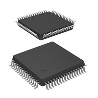
MCU 3/5V 32K J-TEMP POR&LVD 64-L
Manufacturer
Renesas Electronics America
Series
H8® H8/300H Tinyr
Datasheet
1.DF36057GFZV.pdf
(594 pages)
Specifications of DF36034GFPJ
Core Processor
H8/300H
Core Size
16-Bit
Speed
20MHz
Connectivity
CAN, SCI, SSU
Peripherals
LVD, POR, PWM, WDT
Number Of I /o
45
Program Memory Size
32KB (32K x 8)
Program Memory Type
FLASH
Ram Size
2K x 8
Voltage - Supply (vcc/vdd)
3 V ~ 5.5 V
Data Converters
A/D 8x10b
Oscillator Type
Internal
Operating Temperature
-40°C ~ 85°C
Package / Case
64-LQFP
Lead Free Status / RoHS Status
Contains lead / RoHS non-compliant
Eeprom Size
-
Other names
HD64F36034GFPJ
HD64F36034GFPJ
HD64F36034GFPJ


Section 2 CPU
2.8
2.8.1
The address space of this LSI includes empty areas in addition to the ROM, RAM, and on-chip
I/O registers areas available to the user. When data is transferred from CPU to empty areas, the
transferred data will be lost. This action may also cause the CPU to malfunction. When data is
transferred from an empty area to CPU, the contents of the data cannot be guaranteed.
2.8.2
EEPMOV is a block-transfer instruction and transfers the byte size of data indicated by R4L,
which starts from the address indicated by R5, to the address indicated by R6. Set R4L and R6 so
that the end address of the destination address (value of R6 R4L) does not exceed H'FFFF (the
value of R6 must not change from H'FFFF to H'0000 during execution).
2.8.3
The BSET, BCLR, BNOT, BST, and BIST instructions read data from the specified address in
byte units, manipulate the data of the target bit, and write data to the same address again in byte
units. Special care is required when using these instructions in cases where two registers are
assigned to the same address, or when a bit is directly manipulated for a port or a register
containing a write-only bit, because this may rewrite data of a bit other than the bit to be
manipulated.
(1)
Example 1: Bit manipulation for the timer load register and timer counter
(Applicable for timer B1 in the H8/36057 Group and H8/36037 Group.)
Figure 2.13 shows an example of a timer in which two timer registers are assigned to the same
address. When a bit-manipulation instruction accesses the timer load register and timer counter of
a reloadable timer, since these two registers share the same address, the following operations takes
place.
1. Data is read in byte units.
2. The CPU sets or resets the bit to be manipulated with the bit-manipulation instruction.
3. The written data is written again in byte units to the timer load register.
Rev. 4.00 Mar. 15, 2006 Page 42 of 556
REJ09B0026-0400
Bit manipulation for two registers assigned to the same address
Usage Notes
Notes on Data Access to Empty Areas
EEPMOV Instruction
Bit-Manipulation Instruction
Related parts for DF36034GFPJ
Image
Part Number
Description
Manufacturer
Datasheet
Request
R

Part Number:
Description:
Headers & Wire Housings 20P PLUG METAL COVER
Manufacturer:
Hirose Electric Co Ltd
Part Number:
Description:
Headers & Wire Housings 25P PLUG METAL COVER
Manufacturer:
Hirose Electric Co Ltd
Part Number:
Description:
Headers & Wire Housings 15P PLUG METAL COVER
Manufacturer:
Hirose Electric Co Ltd

Part Number:
Description:
0.4 Mm Pitch, 1.5 Mm Mated Height, Board-to-fine Coaxial Cable Connectors
Manufacturer:
Hirose Electric
Datasheet:
Part Number:
Description:
CONN RECEPT 40POS 0.4MM SMD GOLD
Manufacturer:
Hirose Electric Co Ltd
Datasheet:

Part Number:
Description:
KIT STARTER FOR M16C/29
Manufacturer:
Renesas Electronics America
Datasheet:

Part Number:
Description:
KIT STARTER FOR R8C/2D
Manufacturer:
Renesas Electronics America
Datasheet:

Part Number:
Description:
R0K33062P STARTER KIT
Manufacturer:
Renesas Electronics America
Datasheet:

Part Number:
Description:
KIT STARTER FOR R8C/23 E8A
Manufacturer:
Renesas Electronics America
Datasheet:

Part Number:
Description:
KIT STARTER FOR R8C/25
Manufacturer:
Renesas Electronics America
Datasheet:

Part Number:
Description:
KIT STARTER H8S2456 SHARPE DSPLY
Manufacturer:
Renesas Electronics America
Datasheet:

Part Number:
Description:
KIT STARTER FOR R8C38C
Manufacturer:
Renesas Electronics America
Datasheet:

Part Number:
Description:
KIT STARTER FOR R8C35C
Manufacturer:
Renesas Electronics America
Datasheet:

Part Number:
Description:
KIT STARTER FOR R8CL3AC+LCD APPS
Manufacturer:
Renesas Electronics America
Datasheet:
Part Number:
Description:
KIT STARTER FOR RX610
Manufacturer:
Renesas Electronics America
Datasheet: