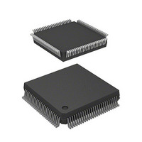
HD6417034AFI20 Renesas Electronics America, HD6417034AFI20 Datasheet - Page 217

HD6417034AFI20
Manufacturer Part Number
HD6417034AFI20
Description
IC SUPERH MPU ROMLESS 112QFP
Manufacturer
Renesas Electronics America
Series
SuperH® SH7030r
Datasheet
1.HD6417034AFI20.pdf
(689 pages)
Specifications of HD6417034AFI20
Core Processor
SH-1
Core Size
32-Bit
Speed
20MHz
Connectivity
EBI/EMI, SCI
Peripherals
DMA, POR, PWM, WDT
Number Of I /o
32
Program Memory Type
ROMless
Ram Size
4K x 8
Voltage - Supply (vcc/vdd)
4.5 V ~ 5.5 V
Data Converters
A/D 8x10b
Oscillator Type
Internal
Operating Temperature
-20°C ~ 75°C
Package / Case
112-QFP
Lead Free Status / RoHS Status
Contains lead / RoHS non-compliant
Eeprom Size
-
Program Memory Size
-
Available stocks
Company
Part Number
Manufacturer
Quantity
Price
Company:
Part Number:
HD6417034AFI20
Manufacturer:
Renesas Electronics America
Quantity:
10 000
Company:
Part Number:
HD6417034AFI20V
Manufacturer:
Renesas Electronics America
Quantity:
10 000
- Current page: 217 of 689
- Download datasheet (5Mb)
Bit 3—Transfer Size Bit (TS): TS selects the transfer unit size. If the on-chip supporting module
that is the source or destination of the transfer can only be accessed in bytes, byte must be selected
with this bit. The TS bit is initialized to 0 by a resets and in standby mode.
Bit 3: TS
0
1
Bit 2—Interrupt Enable Bit (IE): IE determines whether or not to request a CPU interrupt at the
end of a DMA transfer. When the IE bit is set to 1, an interrupt (DEI) request is sent to the CPU
when the TE bit is set. The IE bit is initialized to 0 by a reset and in standby mode.
Bit 2: IE
0
1
Bit 1—Transfer End Flag Bit (TE): TE indicates that the transfer has ended. When a DMA
transfer ends normally and the value in the DMA transfer count register (TCR) becomes 0, the TE
bit is set to 1. This flag is not set if the transfer ends because of an NMI interrupt or address error,
or because the DE bit or the DME bit in the DMA operation register (DMAOR) was cleared. To
clear the TE bit, read 1 from it and then write 0.
When this flag is set, setting the DE bit to 1 does not enable a DMA transfer. The TE bit is
initialized to 0 by a reset and in standby mode.
Bit 1: TE
0
1
Bit 0—DMA Enable Bit (DE): DE enables or disables DMA transfers. In auto-request mode, the
transfer starts when this bit or the DME bit in DMAOR is set to 1. The TE bit and the NMIF and
AE bits in DMAOR must be all cleared to 0. In external request mode or on-chip supporting
module request mode, the transfer begins when the DMA transfer request is received from a
device or on-chip supporting module, provided this bit and the DME bit are set to 1. As with auto
request mode, the TE bit and the NMIF and AE bits must be all cleared to 0. The transfer can be
stopped by clearing this bit to 0.
Description
Byte (8 bits)
Word (16 bits)
Description
Interrupt request disabled
Interrupt request enabled
Description
DMA has not ended or was aborted
To clear TE, the CPU must read TE after it has been set to 1, then write a 0 in
this bit
DMA has ended normally
Section 9 Direct Memory Access Controller (DMAC)
Rev. 7.00 Jan 31, 2006 page 189 of 658
REJ09B0272-0700
(Initial value)
(Initial value)
(Initial value)
Related parts for HD6417034AFI20
Image
Part Number
Description
Manufacturer
Datasheet
Request
R

Part Number:
Description:
KIT STARTER FOR M16C/29
Manufacturer:
Renesas Electronics America
Datasheet:

Part Number:
Description:
KIT STARTER FOR R8C/2D
Manufacturer:
Renesas Electronics America
Datasheet:

Part Number:
Description:
R0K33062P STARTER KIT
Manufacturer:
Renesas Electronics America
Datasheet:

Part Number:
Description:
KIT STARTER FOR R8C/23 E8A
Manufacturer:
Renesas Electronics America
Datasheet:

Part Number:
Description:
KIT STARTER FOR R8C/25
Manufacturer:
Renesas Electronics America
Datasheet:

Part Number:
Description:
KIT STARTER H8S2456 SHARPE DSPLY
Manufacturer:
Renesas Electronics America
Datasheet:

Part Number:
Description:
KIT STARTER FOR R8C38C
Manufacturer:
Renesas Electronics America
Datasheet:

Part Number:
Description:
KIT STARTER FOR R8C35C
Manufacturer:
Renesas Electronics America
Datasheet:

Part Number:
Description:
KIT STARTER FOR R8CL3AC+LCD APPS
Manufacturer:
Renesas Electronics America
Datasheet:

Part Number:
Description:
KIT STARTER FOR RX610
Manufacturer:
Renesas Electronics America
Datasheet:

Part Number:
Description:
KIT STARTER FOR R32C/118
Manufacturer:
Renesas Electronics America
Datasheet:

Part Number:
Description:
KIT DEV RSK-R8C/26-29
Manufacturer:
Renesas Electronics America
Datasheet:

Part Number:
Description:
KIT STARTER FOR SH7124
Manufacturer:
Renesas Electronics America
Datasheet:

Part Number:
Description:
KIT STARTER FOR H8SX/1622
Manufacturer:
Renesas Electronics America
Datasheet:

Part Number:
Description:
KIT DEV FOR SH7203
Manufacturer:
Renesas Electronics America
Datasheet:


