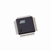
AT91SAM7S32-AU-001 Atmel, AT91SAM7S32-AU-001 Datasheet - Page 375

AT91SAM7S32-AU-001
Manufacturer Part Number
AT91SAM7S32-AU-001
Description
IC ARM7 MCU 32BIT 32K 48LQFP
Manufacturer
Atmel
Series
AT91SAMr
Specifications of AT91SAM7S32-AU-001
Core Processor
ARM7
Core Size
16/32-Bit
Speed
55MHz
Connectivity
I²C, SPI, SSC, UART/USART
Peripherals
Brown-out Detect/Reset, POR, PWM, WDT
Number Of I /o
21
Program Memory Size
32KB (32K x 8)
Program Memory Type
FLASH
Ram Size
8K x 8
Voltage - Supply (vcc/vdd)
1.65 V ~ 1.95 V
Data Converters
A/D 8x10b
Oscillator Type
Internal
Operating Temperature
-40°C ~ 85°C
Package / Case
48-LQFP
For Use With
AT91SAM7S-EK - KIT EVAL FOR ARM AT91SAM7S
Lead Free Status / RoHS Status
Lead free / RoHS Compliant
Eeprom Size
-
Other names
AT91SAM7S32-AU001
Available stocks
Company
Part Number
Manufacturer
Quantity
Price
- Current page: 375 of 779
- Download datasheet (11Mb)
Figure 31-20. Receiver Behavior when Operating with Hardware Handshaking
6175K–ATARM–30-Aug-10
RXBUFF
US_CR
Write
RXD
RTS
RXEN = 1
Figure 31-19. Connection with a Remote Device for Hardware Handshaking
Setting the USART to operate with hardware handshaking is performed by writing the
USART_MODE field in the Mode Register (US_MR) to the value 0x2.
The USART behavior when hardware handshaking is enabled is the same as the behavior in
standard synchronous or asynchronous mode, except that the receiver drives the RTS pin as
described below and the level on the CTS pin modifies the behavior of the transmitter as
described below. Using this mode requires using the PDC channel for reception. The transmitter
can handle hardware handshaking in any case.
Figure 31-20
pin is driven high if the receiver is disabled and if the status RXBUFF (Receive Buffer Full) com-
ing from the PDC channel is high. Normally, the remote device does not start transmitting while
its CTS pin (driven by RTS) is high. As soon as the Receiver is enabled, the RTS falls, indicating
to the remote device that it can start transmitting. Defining a new buffer to the PDC clears the
status bit RXBUFF and, as a result, asserts the pin RTS low.
Figure 31-21
pin disables the transmitter. If a character is being processing, the transmitter is disabled only
after the completion of the current character and transmission of the next character happens as
soon as the pin CTS falls.
Figure 31-21. Transmitter Behavior when Operating with Hardware Handshaking
shows how the transmitter operates if hardware handshaking is enabled. The CTS
shows how the receiver operates if hardware handshaking is enabled. The RTS
CTS
TXD
USART
TXD
RXD
CTS
RTS
AT91SAM7S Series Preliminary
RXD
TXD
RTS
CTS
Remote
Device
RXDIS = 1
375
Related parts for AT91SAM7S32-AU-001
Image
Part Number
Description
Manufacturer
Datasheet
Request
R

Part Number:
Description:
Manufacturer:
ATMEL Corporation
Datasheet:

Part Number:
Description:
AT91 ARM Thumb-based Microcontrollers
Manufacturer:
ATMEL [ATMEL Corporation]
Datasheet:

Part Number:
Description:
IC ARM7 MCU FLASH 32K 48QFN
Manufacturer:
Atmel
Datasheet:

Part Number:
Description:
IC MCU ARM7 32KB FLASH 48LQFP
Manufacturer:
Atmel
Datasheet:

Part Number:
Description:
IC MCU ARM7 32KB FLASH 48-VQFN
Manufacturer:
Atmel
Datasheet:

Part Number:
Description:
DEV KIT FOR AVR/AVR32
Manufacturer:
Atmel
Datasheet:

Part Number:
Description:
INTERVAL AND WIPE/WASH WIPER CONTROL IC WITH DELAY
Manufacturer:
ATMEL Corporation
Datasheet:

Part Number:
Description:
Low-Voltage Voice-Switched IC for Hands-Free Operation
Manufacturer:
ATMEL Corporation
Datasheet:

Part Number:
Description:
MONOLITHIC INTEGRATED FEATUREPHONE CIRCUIT
Manufacturer:
ATMEL Corporation
Datasheet:

Part Number:
Description:
AM-FM Receiver IC U4255BM-M
Manufacturer:
ATMEL Corporation
Datasheet:

Part Number:
Description:
Monolithic Integrated Feature Phone Circuit
Manufacturer:
ATMEL Corporation
Datasheet:

Part Number:
Description:
Multistandard Video-IF and Quasi Parallel Sound Processing
Manufacturer:
ATMEL Corporation
Datasheet:


