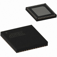
ATA5428-PLQW Atmel, ATA5428-PLQW Datasheet - Page 13

ATA5428-PLQW
Manufacturer Part Number
ATA5428-PLQW
Description
IC TXRX WIDEBND 433/868MHZ 48QFN
Manufacturer
Atmel
Specifications of ATA5428-PLQW
Frequency
433MHz, 868MHz
Data Rate - Maximum
20kbps
Modulation Or Protocol
ASK, FSK
Applications
Alarm and Security Systems, RKE
Power - Output
10dBm
Sensitivity
-112.5dBm
Voltage - Supply
2.4 V ~ 3.6 V or 4.4 V ~ 6.6 V
Current - Receiving
10.5mA
Current - Transmitting
10mA
Data Interface
PCB, Surface Mount
Antenna Connector
PCB, Surface Mount
Operating Temperature
-40°C ~ 85°C
Package / Case
48-VQFN Exposed Pad, 48-HVQFN, 48-SQFN, 48-DHVQFN
Operating Temperature (min)
-40C
Operating Temperature (max)
85C
Operating Temperature Classification
Industrial
Product Depth (mm)
7mm
Product Height (mm)
0.9mm
Product Length (mm)
7mm
Lead Free Status / RoHS Status
Lead free / RoHS Compliant
Memory Size
-
Lead Free Status / Rohs Status
Compliant
Other names
ATA5428-PLQHCT
ATA5428-PLQHCT
ATA5428-PLQWCT
ATA5428-PLQHCT
ATA5428-PLQWCT
Available stocks
Company
Part Number
Manufacturer
Quantity
Price
Company:
Part Number:
ATA5428-PLQW
Manufacturer:
LITELINK
Quantity:
106
Part Number:
ATA5428-PLQW
Manufacturer:
ATMEL/爱特梅尔
Quantity:
20 000
4841D–WIRE–10/07
Figure 3-2.
As can be seen in
perature has an influence of about +1.5/–0.7 dB, and a frequency offset of ±65 kHz also
influences by about ±1 dB. All these influences, combined with the sensitivity of a typical IC, are
then within a range of –103.7 dBm and –107.3 dBm over temperature, supply voltage and fre-
quency offset which is –105.5 dBm ±1.8dB. The integrated IF filter has an additional production
tolerance of only ±7 kHz, hence, a frequency offset between the receiver and the transmitter of
±58 kHz can be accepted for XTAL and XTO tolerances.
Note:
This small sensitivity spread over supply voltage, frequency offset and temperature is very
unusual in such a receiver. It is achieved by an internal, very fast and automatic frequency cor-
rection in the FSK demodulator after the IF filter, which leads to a higher system margin. This
frequency correction tracks the input frequency very quickly; if, however, the input frequency
makes a larger step (for example, if the system changes between different communication part-
ners), the receiver has to be restarted. This can be done by switching back to IDLE mode and
then again to RX mode. For that purpose, an automatic mode is also available. This automatic
mode switches to IDLE mode and back into RX mode every time a bit error occurs.
Control Logic” on page
For the demodulator used in the ATA5423/ATA5425, the tolerable frequency offset does not
change with the data frequency, hence, the value of ±58 kHz is valid for up to 1
-110
-109
-108
-106
-105
-104
-103
-102
-101
-100
-107
-99
-98
-97
-96
-95
-100
Measured Sensitivity 433.92 MHz/FSK/20 Kbit/s/±16 kHz/Manchester versus
Frequency Offset, Temperature and Supply Voltage
-80
Figure 3-2 on page 13
-60
ATA5423/ATA5425/ATA5428/ATA5429
36.)
-40
Frequency Offset (kHz)
-20
0
the supply voltage has almost no influence. The tem-
20
40
60
80
100
V
V
V
V
V
V
V
V
V
S
S
S
S
S
S
S
S
S
= 2.4V T
= 3.0V T
= 3.6V T
= 2.4V T
= 3.0V T
= 3.6V T
= 2.4V T
= 3.0V T
= 3.6V T
Kbit/s
amb
amb
amb
amb
amb
amb
amb
amb
amb
= -40 C
= -40 C
= -40 C
= +25 C
= +25 C
= +25 C
= +105 C
= +105 C
= +105 C
(See “Digital
.
13


