FSBB15CH60C Fairchild Semiconductor, FSBB15CH60C Datasheet - Page 18
FSBB15CH60C
Manufacturer Part Number
FSBB15CH60C
Description
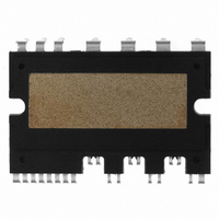
IC POWER MOD SPM 600V SPM27CC
Manufacturer
Fairchild Semiconductor
Series
SPM™r
Type
IGBTr
Specifications of FSBB15CH60C
Configuration
3 Phase
Current
15A
Voltage
600V
Voltage - Isolation
2500Vrms
Package / Case
SPM27CC
Transistor Polarity
N Channel
Dc Collector Current
15A
Collector Emitter Voltage Vces
2V
Power Dissipation Pd
55W
Collector Emitter Voltage V(br)ceo
600V
Operating Temperature Range
-40°C To
Operating Temperature (max)
150C
Operating Temperature (min)
-40C
Pin Count
27
Mounting
Through Hole
Case Length
44mm
Case Height
5.5mm
Screening Level
Automotive
Lead Free Status / RoHS Status
Lead free / RoHS Compliant
Available stocks
Company
Part Number
Manufacturer
Quantity
Price
Company:

Part Number:
FSBB15CH60C
Manufacturer:
CYPRESS
Quantity:
5 610
Part Number:
FSBB15CH60C
Manufacturer:
FSC/ONهڈ¯çœ‹è´§
Quantity:
20 000


2008-03-03
Short-Current Detection Pins
Fault Output Pin
Fault Out Duration Time Selection Pin
Positive DC-Link Pin
Negative DC-Link Pins
Pin : C
Pin : F
Pin : C
Pin : P
Pin : N
• The current sensing shunt resistor should be connected between the pin C
• The shunt resistor should be selected to meet the detection levels matched for the specific
• The connection length between the shunt resistor and C
• This is the fault output alarm pin. An active low output is given on this pin for a fault state
• The V
• This is the pin for selecting the fault out pulse length.
• An external capacitor should be connected between this pin and COM to set the fault out pulse
• The fault-out pulse width t
• This is the DC-link positive power supply pin of the inverter.
• It is internally connected to the collectors of the high-side IGBTs.
• In order to suppress the surge voltage caused by the DC-link wiring or PCB pattern inductance,
• These are the DC-link negative power supply pins (power ground) of the inverter.
• These pins are connected to the low-side IGBT emitters of the each phase.
ground COM to detect short-current (reference Fig. 7.4)
application. An RC filter should be connected to the pin C
condition in the SPM. The alarmed conditions are SC (Short Circuit) or low-side bias UV (Under
Voltage) operation.
logic power supply with approximately 4.7kΩ resistance.
length.
following approximate equation : C
LVIC)
connect a smoothing filter capacitor close to this pin. (Typically Metallized Film Capacitors are
used)
O
SC
FOD
U
, N
V
FO
, N
output is of open collector configured. The F
W
FOD
depends on the capacitance value of C
FOD
V4 Mini DIP SPM Application Note (2008-03-03)
= 18.3 x 10
18
FAIRCHILD SEMICONDUCTOR - Smart Power Module
-6
O
x T
SC
signal line should be pulled up to the 5V
FOD
SC
pin should be minimized.
to eliminate noise.
[F]. (18.3 is internal setting value of
FOD
SC
according to the
and the low-side
Related parts for FSBB15CH60C
Image
Part Number
Description
Manufacturer
Datasheet
Request
R

Part Number:
Description:
Fairchild Semiconductor [IGBT MODULE]
Manufacturer:
Fairchild Semiconductor
Datasheet:

Part Number:
Description:
Discrete Semiconductor Modules
Manufacturer:
Fairchild Semiconductor
Part Number:
Description:
Discrete Semiconductor Modules
Manufacturer:
Fairchild Semiconductor
Part Number:
Description:
This N-Channel MOSFET is produced using Fairchild Semiconductor’s advanced Power Trench® process
Manufacturer:
Fairchild Semiconductor
Datasheet:
Part Number:
Description:
This N-Channel MOSFET is produced using Fairchild Semiconductor’s advanced Power Trench® process
Manufacturer:
Fairchild Semiconductor
Datasheet:
Part Number:
Description:
This N-Channel MOSFET is produced using Fairchild Semiconductor’s advanced PowerTrench® process
Manufacturer:
Fairchild Semiconductor
Datasheet:
Part Number:
Description:
This N-Channel MOSFET is produced using Fairchild Semiconductor’s advanced PowerTrench® process
Manufacturer:
Fairchild Semiconductor
Datasheet:
Part Number:
Description:
This N-Channel MOSFET is produced using Fairchild Semiconductor’s advanced Power Trench® process
Manufacturer:
Fairchild Semiconductor
Datasheet:
Part Number:
Description:
This N-Channel logic Level MOSFETs are produced using Fairchild Semiconductor‘s advanced Power Trench® process that has been special tailored to minimize the on-state resistance and yet maintain superior switching performance
Manufacturer:
Fairchild Semiconductor
Datasheet:
Part Number:
Description:
This N-Channel MOSFET is produced using Fairchild Semiconductor’s advanced Power Trench® process
Manufacturer:
Fairchild Semiconductor
Datasheet:
Part Number:
Description:
This N-Channel SyncFET™ is produced using Fairchild Semiconductor’s advanced PowerTrench® process
Manufacturer:
Fairchild Semiconductor
Datasheet:
Part Number:
Description:
This N-Channel SyncFET™ is produced using Fairchild Semiconductor’s advanced PowerTrench® process
Manufacturer:
Fairchild Semiconductor
Datasheet:
Part Number:
Description:
This N-Channel SyncFET™ is produced using Fairchild Semiconductor’s advanced PowerTrench® process
Manufacturer:
Fairchild Semiconductor
Datasheet:
Part Number:
Description:
This N-Channel logic Level MOSFETs are produced using Fairchild Semiconductor‘s advanced Power Trench® process that has been special tailored to minimize the on-state resistance and yet maintain superior switching performance
Manufacturer:
Fairchild Semiconductor
Datasheet:
Part Number:
Description:
This N-Channel MOSFET is produced using Fairchild Semiconductor’s advanced Power Trench® process that has been especially tailored to minimize the on-state resistance and yet maintain superior switching performance
Manufacturer:
Fairchild Semiconductor
Datasheet: