FSBB15CH60C Fairchild Semiconductor, FSBB15CH60C Datasheet - Page 30
FSBB15CH60C
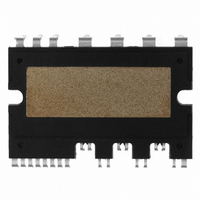
Manufacturer Part Number
FSBB15CH60C
Description
IC POWER MOD SPM 600V SPM27CC
Manufacturer
Fairchild Semiconductor
Series
SPM™r
Type
IGBTr
Specifications of FSBB15CH60C
Configuration
3 Phase
Current
15A
Voltage
600V
Voltage - Isolation
2500Vrms
Package / Case
SPM27CC
Transistor Polarity
N Channel
Dc Collector Current
15A
Collector Emitter Voltage Vces
2V
Power Dissipation Pd
55W
Collector Emitter Voltage V(br)ceo
600V
Operating Temperature Range
-40°C To
Operating Temperature (max)
150C
Operating Temperature (min)
-40C
Pin Count
27
Mounting
Through Hole
Case Length
44mm
Case Height
5.5mm
Screening Level
Automotive
Lead Free Status / RoHS Status
Lead free / RoHS Compliant
Available stocks
Company
Part Number
Manufacturer
Quantity
Price
Company:

Part Number:
FSBB15CH60C
Manufacturer:
CYPRESS
Quantity:
5 610
Part Number:
FSBB15CH60C
Manufacturer:
FSC/ONهڈ¯çœ‹è´§
Quantity:
20 000


7.2 Under-Voltage Protection
insufficient gate driving voltage. A timing chart for this protection is shown in Fig. 7.1.
2008-03-03
Control Voltage Range [V]
a1 : Control supply voltage rises :
a2 : Normal operation : IGBT ON and carrying current.
a3 : Under voltage detection ( UVCCD)
a4 : IGBT OFF in spite of control input condition
a5 : Fault output operation starts
a6 : Under voltage reset ( UVCCR)
a7 : Normal operation : IGBT ON and carrying current
13.5 ~ 16.5 for V
The LVIC has an under voltage lockout function to protect low side IGBTs from operation with
13 ~ 18.5 for V
16.5 ~ 20 for V
18.5 ~ 20 for V
12.5 ~ 13.5
After the voltage rises UVCCR, the circuits start to operate when next input is applied
4 ~ 12.5
Over 20
0 ~ 4
CC
BS
BS
CC
Table 7.1 Mini DIP SPM Functions versus Control Power Supply Voltage
Control IC does not operate. Under voltage lockout and fault output do not operate.
dV/dt noise on the main P-N supply might trigger the IGBTs.
Control IC starts to operate. As the under voltage lockout is set, control input signals are
blocked and a fault signal Fo is generated.
Under voltage lockout is reset. IGBTs will be operated in accordance with the control
gate input. Driving voltage is below the recommended range so V
switching loss will be larger than that under normal condition.
Normal operation. This is the recommended operating condition.
IGBTs are still operated. Because driving voltage is above the recommended range,
IGBTs’ switching is faster. It causes increasing system noise. And peak short circuit
current might be too large for proper operation of the short circuit protection.
Control circuit in the Mini DIP SPM might be damaged.
V4 Mini DIP SPM Application Note (2008-03-03)
Mini DIP SPM Function Operations
30
FAIRCHILD SEMICONDUCTOR - Smart Power Module
CE(sat)
and the
Related parts for FSBB15CH60C
Image
Part Number
Description
Manufacturer
Datasheet
Request
R

Part Number:
Description:
Fairchild Semiconductor [IGBT MODULE]
Manufacturer:
Fairchild Semiconductor
Datasheet:

Part Number:
Description:
Discrete Semiconductor Modules
Manufacturer:
Fairchild Semiconductor
Part Number:
Description:
Discrete Semiconductor Modules
Manufacturer:
Fairchild Semiconductor
Part Number:
Description:
This N-Channel MOSFET is produced using Fairchild Semiconductor’s advanced Power Trench® process
Manufacturer:
Fairchild Semiconductor
Datasheet:
Part Number:
Description:
This N-Channel MOSFET is produced using Fairchild Semiconductor’s advanced Power Trench® process
Manufacturer:
Fairchild Semiconductor
Datasheet:
Part Number:
Description:
This N-Channel MOSFET is produced using Fairchild Semiconductor’s advanced PowerTrench® process
Manufacturer:
Fairchild Semiconductor
Datasheet:
Part Number:
Description:
This N-Channel MOSFET is produced using Fairchild Semiconductor’s advanced PowerTrench® process
Manufacturer:
Fairchild Semiconductor
Datasheet:
Part Number:
Description:
This N-Channel MOSFET is produced using Fairchild Semiconductor’s advanced Power Trench® process
Manufacturer:
Fairchild Semiconductor
Datasheet:
Part Number:
Description:
This N-Channel logic Level MOSFETs are produced using Fairchild Semiconductor‘s advanced Power Trench® process that has been special tailored to minimize the on-state resistance and yet maintain superior switching performance
Manufacturer:
Fairchild Semiconductor
Datasheet:
Part Number:
Description:
This N-Channel MOSFET is produced using Fairchild Semiconductor’s advanced Power Trench® process
Manufacturer:
Fairchild Semiconductor
Datasheet:
Part Number:
Description:
This N-Channel SyncFET™ is produced using Fairchild Semiconductor’s advanced PowerTrench® process
Manufacturer:
Fairchild Semiconductor
Datasheet:
Part Number:
Description:
This N-Channel SyncFET™ is produced using Fairchild Semiconductor’s advanced PowerTrench® process
Manufacturer:
Fairchild Semiconductor
Datasheet:
Part Number:
Description:
This N-Channel SyncFET™ is produced using Fairchild Semiconductor’s advanced PowerTrench® process
Manufacturer:
Fairchild Semiconductor
Datasheet:
Part Number:
Description:
This N-Channel logic Level MOSFETs are produced using Fairchild Semiconductor‘s advanced Power Trench® process that has been special tailored to minimize the on-state resistance and yet maintain superior switching performance
Manufacturer:
Fairchild Semiconductor
Datasheet:
Part Number:
Description:
This N-Channel MOSFET is produced using Fairchild Semiconductor’s advanced Power Trench® process that has been especially tailored to minimize the on-state resistance and yet maintain superior switching performance
Manufacturer:
Fairchild Semiconductor
Datasheet: