FSBB15CH60C Fairchild Semiconductor, FSBB15CH60C Datasheet - Page 45
FSBB15CH60C
Manufacturer Part Number
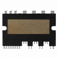
FSBB15CH60C
Description
IC POWER MOD SPM 600V SPM27CC
Manufacturer
Fairchild Semiconductor
Series
SPM™r
Type
IGBTr
Specifications of FSBB15CH60C
Configuration
3 Phase
Current
15A
Voltage
600V
Voltage - Isolation
2500Vrms
Package / Case
SPM27CC
Transistor Polarity
N Channel
Dc Collector Current
15A
Collector Emitter Voltage Vces
2V
Power Dissipation Pd
55W
Collector Emitter Voltage V(br)ceo
600V
Operating Temperature Range
-40°C To
Operating Temperature (max)
150C
Operating Temperature (min)
-40C
Pin Count
27
Mounting
Through Hole
Case Length
44mm
Case Height
5.5mm
Screening Level
Automotive
Lead Free Status / RoHS Status
Lead free / RoHS Compliant
Available stocks
Company
Part Number
Manufacturer
Quantity
Price
Company:

Part Number:
FSBB15CH60C
Manufacturer:
CYPRESS
Quantity:
5 610
Part Number:
FSBB15CH60C
Manufacturer:
FSC/ONهڈ¯çœ‹è´§
Quantity:
20 000


dissipation per device, junction temperature and case reference temperature, respectively. By replacing T
with T
a serial summation of various thermal resistances, R
sink, and R
minimizing R
as well as the minimizing of R
the case temperature T
proportional to the thermal grease thickness and governed by the skill at the assembly site, while R
handled to some extent by selecting an appropriate heat sink.
in Fig. 9.1 should be considered. For pulsed power loss, the thermal capacitance effect delays the rise in
junction temperature, and thus permits a heavier loading of the SPM. Figure 9.2 shows the normalized
thermal impedance curves of FSBB30CH60C, FSBB15CH60C, FSBF10CH60B and FSBF3CH60B. The
2008-03-03
a
The thermal resistance of the SPM is defined in the following equation,
where R
where R
where R
In practical operation, the power loss P
(ambient temperature), the junction-to-ambient thermal resistance R
θ ha
θ ch
θ ja
θ ch
θ jc
and R
is heat sink thermal resistance, respectively. From the equation (9.13), it is clear that
(
is contact thermal resistance due to the thermal grease between the package and the heat
o
P
indicates the total thermal performance of the SPM including the heat sink. Basically R
C/W) is the junction-to-case thermal resistance, and P
D
θ ha
Figure 9.1 Transient thermal equivalent circuit with a heatsink.
c
is an essential application factor to maximize the power carrying ability of the SPM
is locked at the fixed ambient temperature T
T
Being ignored
j
θ jc
itself. An infinite heat sink will result if R
C
jc
R
R
R
θ
θ
θ jc
R
ja
jc
θ
R
ja
=
=
θ ca
D
=
R
T
is cyclic and therfore the transient RC equivalent circuit shown
θ
T
j
T
Transient impedance
jc
V4 Mini DIP SPM Application Note (2008-03-03)
P
c
−
j
D
+
P
of each section
−
T
θ jc
D
45
R
c
T
, R
θ
FAIRCHILD SEMICONDUCTOR - Smart Power Module
a
C
ch
θ ch
ch
+
R
and R
R
θ ch
θ
ha
θ ha
T
.
h
θ ch
D
(W), T
θ ja
and R
a
C
. Usually, the value of R
can be obtained as following,
ha
R
j
θ ha
θ ha
(
o
C) and T
are reduced to zero and
T
a
c
(
o
C) are power
θ ha
can be
(9.12)
(9.13)
(9.11)
θ ch
θ ja
is
is
c
Related parts for FSBB15CH60C
Image
Part Number
Description
Manufacturer
Datasheet
Request
R

Part Number:
Description:
Fairchild Semiconductor [IGBT MODULE]
Manufacturer:
Fairchild Semiconductor
Datasheet:

Part Number:
Description:
Discrete Semiconductor Modules
Manufacturer:
Fairchild Semiconductor
Part Number:
Description:
Discrete Semiconductor Modules
Manufacturer:
Fairchild Semiconductor
Part Number:
Description:
This N-Channel MOSFET is produced using Fairchild Semiconductor’s advanced Power Trench® process
Manufacturer:
Fairchild Semiconductor
Datasheet:
Part Number:
Description:
This N-Channel MOSFET is produced using Fairchild Semiconductor’s advanced Power Trench® process
Manufacturer:
Fairchild Semiconductor
Datasheet:
Part Number:
Description:
This N-Channel MOSFET is produced using Fairchild Semiconductor’s advanced PowerTrench® process
Manufacturer:
Fairchild Semiconductor
Datasheet:
Part Number:
Description:
This N-Channel MOSFET is produced using Fairchild Semiconductor’s advanced PowerTrench® process
Manufacturer:
Fairchild Semiconductor
Datasheet:
Part Number:
Description:
This N-Channel MOSFET is produced using Fairchild Semiconductor’s advanced Power Trench® process
Manufacturer:
Fairchild Semiconductor
Datasheet:
Part Number:
Description:
This N-Channel logic Level MOSFETs are produced using Fairchild Semiconductor‘s advanced Power Trench® process that has been special tailored to minimize the on-state resistance and yet maintain superior switching performance
Manufacturer:
Fairchild Semiconductor
Datasheet:
Part Number:
Description:
This N-Channel MOSFET is produced using Fairchild Semiconductor’s advanced Power Trench® process
Manufacturer:
Fairchild Semiconductor
Datasheet:
Part Number:
Description:
This N-Channel SyncFET™ is produced using Fairchild Semiconductor’s advanced PowerTrench® process
Manufacturer:
Fairchild Semiconductor
Datasheet:
Part Number:
Description:
This N-Channel SyncFET™ is produced using Fairchild Semiconductor’s advanced PowerTrench® process
Manufacturer:
Fairchild Semiconductor
Datasheet:
Part Number:
Description:
This N-Channel SyncFET™ is produced using Fairchild Semiconductor’s advanced PowerTrench® process
Manufacturer:
Fairchild Semiconductor
Datasheet:
Part Number:
Description:
This N-Channel logic Level MOSFETs are produced using Fairchild Semiconductor‘s advanced Power Trench® process that has been special tailored to minimize the on-state resistance and yet maintain superior switching performance
Manufacturer:
Fairchild Semiconductor
Datasheet:
Part Number:
Description:
This N-Channel MOSFET is produced using Fairchild Semiconductor’s advanced Power Trench® process that has been especially tailored to minimize the on-state resistance and yet maintain superior switching performance
Manufacturer:
Fairchild Semiconductor
Datasheet: