FSBB15CH60C Fairchild Semiconductor, FSBB15CH60C Datasheet - Page 49
FSBB15CH60C
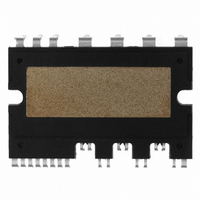
Manufacturer Part Number
FSBB15CH60C
Description
IC POWER MOD SPM 600V SPM27CC
Manufacturer
Fairchild Semiconductor
Series
SPM™r
Type
IGBTr
Specifications of FSBB15CH60C
Configuration
3 Phase
Current
15A
Voltage
600V
Voltage - Isolation
2500Vrms
Package / Case
SPM27CC
Transistor Polarity
N Channel
Dc Collector Current
15A
Collector Emitter Voltage Vces
2V
Power Dissipation Pd
55W
Collector Emitter Voltage V(br)ceo
600V
Operating Temperature Range
-40°C To
Operating Temperature (max)
150C
Operating Temperature (min)
-40C
Pin Count
27
Mounting
Through Hole
Case Length
44mm
Case Height
5.5mm
Screening Level
Automotive
Lead Free Status / RoHS Status
Lead free / RoHS Compliant
Available stocks
Company
Part Number
Manufacturer
Quantity
Price
Company:

Part Number:
FSBB15CH60C
Manufacturer:
CYPRESS
Quantity:
5 610
Part Number:
FSBB15CH60C
Manufacturer:
FSC/ONهڈ¯çœ‹è´§
Quantity:
20 000


temperature. The TSP sampling pulse must provide a sense current equal to that used during the calibration
procedure for obtaining equation (9.14). While monitoring the TSP, adjust the applied power so as to insure a
sufficient rise in T
temperature will generate enough temperature difference to ensure a good measurement resolution. A
typical example is shown in Fig. 9.5.
junction prior to re-applying power. The power and sensing pulse train shown in Fig. 9.5 has a duty cycle of
99.9%, which for all practical purposes is considered to be continuous power. Obviously, most of the total
power is applied to the DUT in Fig. 9.6.
power P is recorded. Using the measured values and equation (9.11), the junction-to-case thermal resistance
R
that is, mounted with an infinite or temperature-controlled heat sink.
heat sink having a large heat carrying capacity. Thermal grease is applied between the SPM and heat sink to
prevent an air gap.
2008-03-03
θ
jc
can be estimated. R
The TSP sampling time must be very short so as not to allow for any appreciable cooling of the
Figure 9.7 shows the thermal resistance measurement environment for SPMs. The SPM is placed on a
Once T
Figure 9.5 Example of a power and sample pulses train during the R
Heating
Power
j
reaches thermal equilibrium, its value along with the reference temperature T
j
. Adjusting the applied power to achieve a T
θ
jc
80ms
here indicates the ability of a device to dissipate power in an ideal environment,
Train of heating pulse with 80ms interval and
sensing pulses with 100us is given typically
V4 Mini DIP SPM Application Note (2008-03-03)
100us
49
FAIRCHILD SEMICONDUCTOR - Smart Power Module
j
increase of about 100 ℃ above the reference
jc
measurement of a SPM-IGBT
Time
c
and applied
Related parts for FSBB15CH60C
Image
Part Number
Description
Manufacturer
Datasheet
Request
R

Part Number:
Description:
Fairchild Semiconductor [IGBT MODULE]
Manufacturer:
Fairchild Semiconductor
Datasheet:

Part Number:
Description:
Discrete Semiconductor Modules
Manufacturer:
Fairchild Semiconductor
Part Number:
Description:
Discrete Semiconductor Modules
Manufacturer:
Fairchild Semiconductor
Part Number:
Description:
This N-Channel MOSFET is produced using Fairchild Semiconductor’s advanced Power Trench® process
Manufacturer:
Fairchild Semiconductor
Datasheet:
Part Number:
Description:
This N-Channel MOSFET is produced using Fairchild Semiconductor’s advanced Power Trench® process
Manufacturer:
Fairchild Semiconductor
Datasheet:
Part Number:
Description:
This N-Channel MOSFET is produced using Fairchild Semiconductor’s advanced PowerTrench® process
Manufacturer:
Fairchild Semiconductor
Datasheet:
Part Number:
Description:
This N-Channel MOSFET is produced using Fairchild Semiconductor’s advanced PowerTrench® process
Manufacturer:
Fairchild Semiconductor
Datasheet:
Part Number:
Description:
This N-Channel MOSFET is produced using Fairchild Semiconductor’s advanced Power Trench® process
Manufacturer:
Fairchild Semiconductor
Datasheet:
Part Number:
Description:
This N-Channel logic Level MOSFETs are produced using Fairchild Semiconductor‘s advanced Power Trench® process that has been special tailored to minimize the on-state resistance and yet maintain superior switching performance
Manufacturer:
Fairchild Semiconductor
Datasheet:
Part Number:
Description:
This N-Channel MOSFET is produced using Fairchild Semiconductor’s advanced Power Trench® process
Manufacturer:
Fairchild Semiconductor
Datasheet:
Part Number:
Description:
This N-Channel SyncFET™ is produced using Fairchild Semiconductor’s advanced PowerTrench® process
Manufacturer:
Fairchild Semiconductor
Datasheet:
Part Number:
Description:
This N-Channel SyncFET™ is produced using Fairchild Semiconductor’s advanced PowerTrench® process
Manufacturer:
Fairchild Semiconductor
Datasheet:
Part Number:
Description:
This N-Channel SyncFET™ is produced using Fairchild Semiconductor’s advanced PowerTrench® process
Manufacturer:
Fairchild Semiconductor
Datasheet:
Part Number:
Description:
This N-Channel logic Level MOSFETs are produced using Fairchild Semiconductor‘s advanced Power Trench® process that has been special tailored to minimize the on-state resistance and yet maintain superior switching performance
Manufacturer:
Fairchild Semiconductor
Datasheet:
Part Number:
Description:
This N-Channel MOSFET is produced using Fairchild Semiconductor’s advanced Power Trench® process that has been especially tailored to minimize the on-state resistance and yet maintain superior switching performance
Manufacturer:
Fairchild Semiconductor
Datasheet: