FSBB15CH60C Fairchild Semiconductor, FSBB15CH60C Datasheet - Page 42
FSBB15CH60C
Manufacturer Part Number
FSBB15CH60C
Description
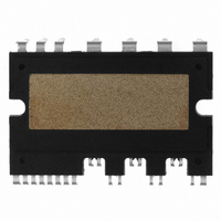
IC POWER MOD SPM 600V SPM27CC
Manufacturer
Fairchild Semiconductor
Series
SPM™r
Type
IGBTr
Specifications of FSBB15CH60C
Configuration
3 Phase
Current
15A
Voltage
600V
Voltage - Isolation
2500Vrms
Package / Case
SPM27CC
Transistor Polarity
N Channel
Dc Collector Current
15A
Collector Emitter Voltage Vces
2V
Power Dissipation Pd
55W
Collector Emitter Voltage V(br)ceo
600V
Operating Temperature Range
-40°C To
Operating Temperature (max)
150C
Operating Temperature (min)
-40C
Pin Count
27
Mounting
Through Hole
Case Length
44mm
Case Height
5.5mm
Screening Level
Automotive
Lead Free Status / RoHS Status
Lead free / RoHS Compliant
Available stocks
Company
Part Number
Manufacturer
Quantity
Price
Company:

Part Number:
FSBB15CH60C
Manufacturer:
CYPRESS
Quantity:
5 610
Part Number:
FSBB15CH60C
Manufacturer:
FSC/ONهڈ¯çœ‹è´§
Quantity:
20 000


9. Power Loss and Dissipation
9.1 Power Loss of SPM
IGBTs and FRDs. The loss during the turn-off steady state can be ignored because it is very small amount
and has little effect on increasing the temperature in the device. The conduction loss depends on the dc
electrical characteristics of the device i.e. saturation voltage. Therefore, it is a function of the conduction
current and the device’s junction temperature. On the other hand the switching loss is determined by the
dynamic characteristics like turn-on/off time and over-voltage/current. Hence, in order to obtain the accurate
switching loss, we should consider the DC-link voltage of the system, the applied switching frequency and
the power circuit layout in addition to the current and temperature.
shown to calculate both losses of the Mini DIP SPM. They are for the case that 3-phase continuous
sinusoidal PWM is adopted. For other cases like 3-phase discontinuous PWMs, please refer to the paper
"Minimum-Loss Strategy for three-Phase PWM Rectifier, IEEE Transactions on Industrial Electronics, Vol. 46,
No. 3, June, 1999 by Dae-Woong Chung and Seung-Ki Sul”.
9.1.1 Conduction Loss
for the IGBT and the diode, respectively.
to be sinusoidal. That is,
conduction loss of one IGBT and diode can be obtained as follows.
2008-03-03
The total power losses in the Mini DIP SPM are composed of conduction and switching losses in the
In this chapter, based on a PWM-inverter system for motor control applications, detailed equations are
The typical characteristics of forward drop voltage are approximated by the following linear equation
Assuming that the switching frequency is high, the output current of the PWM-inverter can be assumed
Where φ is the phase-angle difference between output voltage and current. Using equations (9.1), the
V
R
I
I
= Threshold voltage of IGBT
= on-state slope resistance of IGBT
v
v
i
I
D
=
=
=
I
V
peak
V
I
D
+
cos(
+
R
R
I
D
θ
⋅
i
⋅
−
i
φ
)
V4 Mini DIP SPM Application Note (2008-03-03)
42
V
FAIRCHILD SEMICONDUCTOR - Smart Power Module
R
D
D
= Threshold voltage of diode
= on-state slope resistance of diode
(9.1)
(9.2)
Related parts for FSBB15CH60C
Image
Part Number
Description
Manufacturer
Datasheet
Request
R

Part Number:
Description:
Fairchild Semiconductor [IGBT MODULE]
Manufacturer:
Fairchild Semiconductor
Datasheet:

Part Number:
Description:
Discrete Semiconductor Modules
Manufacturer:
Fairchild Semiconductor
Part Number:
Description:
Discrete Semiconductor Modules
Manufacturer:
Fairchild Semiconductor
Part Number:
Description:
This N-Channel MOSFET is produced using Fairchild Semiconductor’s advanced Power Trench® process
Manufacturer:
Fairchild Semiconductor
Datasheet:
Part Number:
Description:
This N-Channel MOSFET is produced using Fairchild Semiconductor’s advanced Power Trench® process
Manufacturer:
Fairchild Semiconductor
Datasheet:
Part Number:
Description:
This N-Channel MOSFET is produced using Fairchild Semiconductor’s advanced PowerTrench® process
Manufacturer:
Fairchild Semiconductor
Datasheet:
Part Number:
Description:
This N-Channel MOSFET is produced using Fairchild Semiconductor’s advanced PowerTrench® process
Manufacturer:
Fairchild Semiconductor
Datasheet:
Part Number:
Description:
This N-Channel MOSFET is produced using Fairchild Semiconductor’s advanced Power Trench® process
Manufacturer:
Fairchild Semiconductor
Datasheet:
Part Number:
Description:
This N-Channel logic Level MOSFETs are produced using Fairchild Semiconductor‘s advanced Power Trench® process that has been special tailored to minimize the on-state resistance and yet maintain superior switching performance
Manufacturer:
Fairchild Semiconductor
Datasheet:
Part Number:
Description:
This N-Channel MOSFET is produced using Fairchild Semiconductor’s advanced Power Trench® process
Manufacturer:
Fairchild Semiconductor
Datasheet:
Part Number:
Description:
This N-Channel SyncFET™ is produced using Fairchild Semiconductor’s advanced PowerTrench® process
Manufacturer:
Fairchild Semiconductor
Datasheet:
Part Number:
Description:
This N-Channel SyncFET™ is produced using Fairchild Semiconductor’s advanced PowerTrench® process
Manufacturer:
Fairchild Semiconductor
Datasheet:
Part Number:
Description:
This N-Channel SyncFET™ is produced using Fairchild Semiconductor’s advanced PowerTrench® process
Manufacturer:
Fairchild Semiconductor
Datasheet:
Part Number:
Description:
This N-Channel logic Level MOSFETs are produced using Fairchild Semiconductor‘s advanced Power Trench® process that has been special tailored to minimize the on-state resistance and yet maintain superior switching performance
Manufacturer:
Fairchild Semiconductor
Datasheet:
Part Number:
Description:
This N-Channel MOSFET is produced using Fairchild Semiconductor’s advanced Power Trench® process that has been especially tailored to minimize the on-state resistance and yet maintain superior switching performance
Manufacturer:
Fairchild Semiconductor
Datasheet: