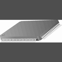
CR16MCS9VJE8 National Semiconductor, CR16MCS9VJE8 Datasheet - Page 109

CR16MCS9VJE8
Manufacturer Part Number
CR16MCS9VJE8
Description
16-Bit Microcontroller IC
Manufacturer
National Semiconductor
Datasheet
1.CR16MCS9VJE8.pdf
(156 pages)
Specifications of CR16MCS9VJE8
Controller Family/series
CR16X
Core Size
16 Bit
Program Memory Size
64K X 8 Flash
Digital Ic Case Style
PQFP
No. Of Pins
80
Mounting Type
Surface Mount
Clock Frequency
25MHz
Lead Free Status / RoHS Status
Contains lead / RoHS non-compliant
Available stocks
Company
Part Number
Manufacturer
Quantity
Price
Company:
Part Number:
CR16MCS9VJE8
Manufacturer:
ON
Quantity:
8 917
Company:
Part Number:
CR16MCS9VJE8-CBB
Manufacturer:
ON
Quantity:
846
Company:
Part Number:
CR16MCS9VJE8-CBC
Manufacturer:
ON
Quantity:
109
Company:
Part Number:
CR16MCS9VJE8-CBD
Manufacturer:
ON
Quantity:
17
Company:
Part Number:
CR16MCS9VJE8-CBE
Manufacturer:
ON
Quantity:
1 950
20.9.7
During remote frame transfer, the buffer registers DATA[3:0]
are “don’t cares”. If a remote frame is transmitted, the con-
tents of these registers are ignored. If a remote frame is re-
SRR
IDE
RTR
ID[28:0]
ADDR
xxxE
xxxC
xxxA
xxx8
xxx6
xxx4
xxx2
xxx0
16
16
16
1 6
1 6
1 6
1 6
1 6
Storage of Remote Messages
BUFFER
register
CNTSTAT
DATA0
DATA1
DATA2
DATA3
TSTP
ID1
ID0
Substitute Remote Request. SRR replaces the
RTR bit used in standard frames at this bit po-
sition. The SRR bit needs to be set to “1” by the
user.
Identifier Extension. IDE is set to “0” to indicate
that the message is a standard frame using 11
identifier bits. If IDE is set to “1”, the message
stored in the buffer is handled as an extended
frame.
Remote Transmission Request. RTR is set to
“1” to indicate that the message is a remote
frame. For a data frame, the RTR bit is set to
“0”.
The ID bits 28 to 0 are used to build the 29-bit
identifier of an extended frame. The ID1 buffer
bits ID28 to ID18 are used for the 11 standard
frame identifier bits.
TSTP15 TSTP14 TSTP13
DLC3
ID28
ID14
15
DLC2
ID27
ID13
14
DLC1
ID26
ID12
13
TSTP12
DLC0
ID25
ID11
Table 30 Extended Remote Frame
12
TSTP11
ID24
ID10
11
TSTP10
ID23
10
ID9
Reserved
109
TSTP
ID22
ceived, the contents of these registers will be overwritten with
invalid data. The structure of a message buffer set up for a
remote frame with extended identifier is shown in Table30.
ID8
20.9.8
The CAN Global Configuration Register (CGCR) is a 16-bit
wide register used to:
• enable/disable the CR16CAN
• configure the BUFFLOCK function for the message buffer
• enable/disable the time stamp synchronization
• set the logic levels of the CAN Input/Output pins
• choose the data storage direction (DDIR)
• select the error interrupt type (EIT)
• enable/disable diagnostic functions
CANEN
CTX
9
9
IGNACK LO DDIR TSTPEN BUFFLOCK CRX CTX CANEN
15
0...14
CANRX/CANTX
don’t care
don’t care
don’t care
don’t care
7
Reserved
TSTP
ID21
ID7
8
8
CAN Global Configuration Register (CGCR)
6
TSTP
PRI3
ID20
ID6
7
7
CAN Enable. This bit enables/disables the
CR16CAN. When the CR16CAN is disabled,
all internal states and the TEC and REC
counter registers are cleared. In addition the
CR16CAN clock is disabled. All CR16CAN
control registers and the contents of the mes-
sage memory are left unchanged.
The user needs to make sure that no message
is pending for transmission before the
CR16CAN is disabled.
“0” CR16CAN is disabled
“1” CR16CAN is enabled
Control Transmit. This bit configures the logic
level of the CAN transmit pin CANTX.
“0” dominate state is “0”; recessive state is “1”
12
5
TSTP
PRI2
ID19
ID5
6
6
EIT DIAGEN INTERNAL LOOPBACK
11
4
TSTP
ID18
PRI1
ID4
5
5
10
r/w
r/w
0
0
TSTP
SRR
PRI0
ID3
4
4
3
TSTP
ST3
IDE
ID2
3
3
9
TSTP
www.national.com
ID17
ST2
ID1
2
2
2
TSTP
1
ID16
ST1
ID0
1
1
8
TSTP
ID15
RTR
ST0
0
0
0


