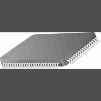
CR16MCS9VJE8 National Semiconductor, CR16MCS9VJE8 Datasheet - Page 49

CR16MCS9VJE8
Manufacturer Part Number
CR16MCS9VJE8
Description
16-Bit Microcontroller IC
Manufacturer
National Semiconductor
Datasheet
1.CR16MCS9VJE8.pdf
(156 pages)
Specifications of CR16MCS9VJE8
Controller Family/series
CR16X
Core Size
16 Bit
Program Memory Size
64K X 8 Flash
Digital Ic Case Style
PQFP
No. Of Pins
80
Mounting Type
Surface Mount
Clock Frequency
25MHz
Lead Free Status / RoHS Status
Contains lead / RoHS non-compliant
Available stocks
Company
Part Number
Manufacturer
Quantity
Price
Company:
Part Number:
CR16MCS9VJE8
Manufacturer:
ON
Quantity:
8 917
Company:
Part Number:
CR16MCS9VJE8-CBB
Manufacturer:
ON
Quantity:
846
Company:
Part Number:
CR16MCS9VJE8-CBC
Manufacturer:
ON
Quantity:
109
Company:
Part Number:
CR16MCS9VJE8-CBD
Manufacturer:
ON
Quantity:
17
Company:
Part Number:
CR16MCS9VJE8-CBE
Manufacturer:
ON
Quantity:
1 950
15.0 Multi-Function Timer
The Multi-Function Timer (MFT16) module contains two inde-
pendent timer/counter units called MFT1 and MFT2, each
containing a pair of 16-bit timer/counters. Each timer/counter
unit offers a choice of clock sources for operation and can be
configured to operate in any of the following modes:
• Processor-Independent Pulse Width Modulation (PWM)
• Dual Input Capture mode, which measures the elapsed
• Dual Independent Timer mode, which generates system
• Single Input Capture and Single Timer mode, which pro-
15.1.1
The Timer/Counter block contains the following functional
blocks:
In a power-saving mode that uses the low-frequency (32.768
kHz) clock as the system clock, the synchronization circuit
requires that the slow clock operate at no more than one-
fourth the speed of the 32.768 kHz system clock.
15.1.2
The Clock Source block generates the signals used to clock
the two timer/counter registers. The internal structure of the
Clock Source block is shown in Figure12.
mode, which generates pulses of a specified width and
duty cycle, and which also provides a general-purpose
timer/counter
time between occurrences of external events, and which
also provides a general-purpose timer/counter
timing signals or counts occurrences of external events
vides one external event counter and one system timer
— two 16-bit counters, Timer/Counter I (TnCNT1) and
— two 16-bit reload/capture registers, TnCRA and
— control logic necessary to configure the timer to oper-
— interrupt control and I/O control logic
Timer/Counter II (TnCNT2)
TnCRB
ate in any of the four operating modes
Timer/Counter Block
Clock Source Block
System
Clock
Clock Source
External Event
Figure 11. Multi-Function Timer Block Diagram
Timer/Counter
Reload/Capture
Reload/Capture
Timer/Counter
Timer/Counter
PWM/Capture/Counter
Mode Select + Control
A
B
1
2
49
The two timer units, MFT1 and MFT2, are identical in opera-
tion and separately programmable. Each timer unit uses two
I/O pins, called T1A and T1B (for Timer MFT1) or T2A and
T2B (for Timer MFT2). The timer I/O pins are alternate func-
tions of the Port F I/O pins.
In the description of the timers, the lower-case letter “n” rep-
resents the timer number, either 1 or 2. For example, “TnA”
means I/O pin T1A or T2A.
15.1
Figure11 is a block diagram showing the internal structure of
each timer. There are two main functional blocks: a Timer/
Counter and Action block and a Clock Source block. The
Timer/Counter and Action block contains two separate timer/
counter units, called Timer/Counter I and Timer/Counter II (a
total of four timer/counter unit in both MFT1 and MFT2).
Counter Clock Source Select
There are two clock source selectors that allow the software
to independently select the clock source for each of the two
16-bit counters from any one of the following sources:
Prescaler
The 5-bit clock prescaler allows the software to run the timer
with a prescaled clock signal. The prescaler consists of a 5-
bit read/write prescaler register (TnPRSC) and a 5-bit down
counter. The system clock is divided by the value contained
in the prescaler register plus 1. Thus, the timer clock period
can be set to any value from 1 to 32 divisions of the system
clock period. The prescaler register and down counter are
both cleared upon reset.
— no clock (which stops the counter)
— prescaled system clock
— external event count based on TnB
— pulse accumulate mode based on TnB
— slow clock (derived from the low-frequency oscillator or
divided from the high-speed oscillator)
Action
TIMER STRUCTURE
Interrupt B
Interrupt A
www.national.com
TnA
TnB


