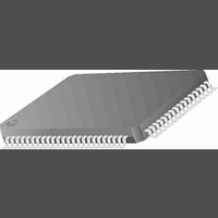
CR16MCS9VJE8 National Semiconductor, CR16MCS9VJE8 Datasheet - Page 59

CR16MCS9VJE8
Manufacturer Part Number
CR16MCS9VJE8
Description
16-Bit Microcontroller IC
Manufacturer
National Semiconductor
Datasheet
1.CR16MCS9VJE8.pdf
(156 pages)
Specifications of CR16MCS9VJE8
Controller Family/series
CR16X
Core Size
16 Bit
Program Memory Size
64K X 8 Flash
Digital Ic Case Style
PQFP
No. Of Pins
80
Mounting Type
Surface Mount
Clock Frequency
25MHz
Lead Free Status / RoHS Status
Contains lead / RoHS non-compliant
Available stocks
Company
Part Number
Manufacturer
Quantity
Price
Company:
Part Number:
CR16MCS9VJE8
Manufacturer:
ON
Quantity:
8 917
Company:
Part Number:
CR16MCS9VJE8-CBB
Manufacturer:
ON
Quantity:
846
Company:
Part Number:
CR16MCS9VJE8-CBC
Manufacturer:
ON
Quantity:
109
Company:
Part Number:
CR16MCS9VJE8-CBD
Manufacturer:
ON
Quantity:
17
Company:
Part Number:
CR16MCS9VJE8-CBE
Manufacturer:
ON
Quantity:
1 950
16.1.1
Each timer subsystem may be configured to generate two
fully independent PWM waveforms on the respective TIOx
pins. In this mode, the counter COUNTx is split and operates
as two independent 8-bit counters. Each counter increments
at the rate determined by the clock prescaler.
Each of the two 8-bit counters may be started and stopped
separately via the associated TxRUN bits. Once either of the
two 8-bit timers is running the clock prescaler starts counting.
Once the clock prescaler counter value matches the value of
the associated CxPRSC register field, COUNTx is incre-
mented.
The period time is determined by the following formula:
The duty cycle in percent is calculated as follows:
If the duty cycle register (DTYCAPx) holds a value which is
greater then the value held in the period register (PERCAPx)
the TIOx output will remain at the opposite of its default value
which corresponds to a duty cycle of 100%. If the duty cycle
register (DTYCAPx) register holds a value of 00
output will remain at the default value which corresponds to
a duty cycle of 0%. In that case the value contained in the
PERCAPx register is irrelevant. This scheme allows the duty
cycle to be programmed in a range from 0% to 100%.
In order to allow fully synchronized updates of the period and
duty cycle compare values, the PERCAPx and DTYCAPx
registers are double buffered when operating in PWM mode.
Therefore if the user writes to either the period or duty cycle
PWMperiod = (PERCAPx + 1) * (CxPRSC + 1) * T
DutyCycle[%] = (DTYCAPx / (PERCAPx+1)) *100
Dual 8-bit PWM Mode
TIOx (PxPOL=0)
TIOx (PxPOL=1)
PERCAPx
DTYCAPx
COUNTx
TxRUN=1
00
01
02
03
Figure 19. VTU PWM generation
04
16
, the TIOx
05
CLK
06
07
59
08
The period of the PWM output waveform is determined by
the value of the PERCAPx register. The TIOx output starts at
the default value as pro-grammed via the IOxCTL.PxPOL bit.
Once the counter value reaches the value of the period reg-
ister PERCAPx, the counter is reset to 00
counter increment. Upon the following increment from 00
to 01
fault value.
The duty cycle of the PWM output waveform is controlled by
the DTYCAPx register value. Once the counter value reach-
es the value of the duty cycle register DTYCAPx, the PWM
output TIOx changes back to its default value upon the next
counter increment. Figure19 illustrates this concept.
register while either of the two PWM channels is enabled, the
new value will not take effect until the counter value matches
the previous period value or the timer is stopped.
Reading the PERCAPx or DTYCAPx register will always re-
turn the most recent value written to it.
The counter registers can be written if both 8-bit counters are
stopped. This allows the user to preset the counters before
starting and therefore generate PWM output waveforms with
a phase shift relative to one another. If the counter is written
with a value other then 00
value while TIOx remains at its default value until the first
00
counter is preset to values which are smaller or equal then
the value held in the period register (PERCAPx) the counter
will count up until a match between the counter value and the
PERCAPx register value occurs. The counter will then be re-
set to 00
counter may be written with a value which is greater then the
09
16
0A
16
to 01
, the TIOx output will change to the opposite of the de-
00
16
1 6
01
and continue counting up. Alternatively the
transition of the counter value occurs. If the
02
03
04
1 6
05
it will start incrementing from that
06
07
08
09
www.national.com
16
0A
upon the next
16


