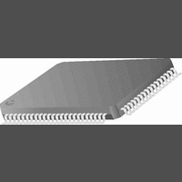
CR16MCS9VJE8 National Semiconductor, CR16MCS9VJE8 Datasheet - Page 120

CR16MCS9VJE8
Manufacturer Part Number
CR16MCS9VJE8
Description
16-Bit Microcontroller IC
Manufacturer
National Semiconductor
Datasheet
1.CR16MCS9VJE8.pdf
(156 pages)
Specifications of CR16MCS9VJE8
Controller Family/series
CR16X
Core Size
16 Bit
Program Memory Size
64K X 8 Flash
Digital Ic Case Style
PQFP
No. Of Pins
80
Mounting Type
Surface Mount
Clock Frequency
25MHz
Lead Free Status / RoHS Status
Contains lead / RoHS non-compliant
Available stocks
Company
Part Number
Manufacturer
Quantity
Price
Company:
Part Number:
CR16MCS9VJE8
Manufacturer:
ON
Quantity:
8 917
Company:
Part Number:
CR16MCS9VJE8-CBB
Manufacturer:
ON
Quantity:
846
Company:
Part Number:
CR16MCS9VJE8-CBC
Manufacturer:
ON
Quantity:
109
Company:
Part Number:
CR16MCS9VJE8-CBD
Manufacturer:
ON
Quantity:
17
Company:
Part Number:
CR16MCS9VJE8-CBE
Manufacturer:
ON
Quantity:
1 950
www.national.com
with ADDATA3. After it loads all four registers, it clears the
START bit and sets the EOC (end of conversion) bit. If the A/
D Converter interrupt is enabled, an interrupt to the CPU is
generated at this time.
22.1.4
In the 4-channel scan, continuous conversion mode, the A/D
Converter performs conversions repeatedly using four adja-
cent input channels.
The software starts conversion operations by setting the
START bit. The A/D Converter performs four A/D conver-
sions in sequence using four adjacent channels, starting with
the specified channel and pausing only for the programmable
sampling delay time. It loads the four results into the A/D data
registers in sequence, starting with ADDATA0 and ending
with ADDATA3. After it loads all four registers, it sets the EOC
(end of conversion) bit. If the A/D Converter interrupt is en-
abled, an interrupt to the CPU is generated at this time.
The START bit remains set until cleared by the software. If
the software does not clear the START bit, the A/D Converter
continues performing conversions, repeating the same se-
quence using the same four input channels and the same se-
quence of data registers. To prevent an overrun error, the
software must read the results from the data registers before
the A/D Converter writes the next result into ADDATA0.
When the software clears the START bit, the A/D Converter
first completes the 4-channel conversion sequence currently
in progress, then stops and sets the EOC bit.
22.2
The software controls the A/D Converter and reads the A/D
results by accessing the ADC registers. There are eight such
registers:
— ADC Status Register (ADCST)
— ADC Control 1 Register (ADCCNT1)
— ADC Control 2 Register (ADCCNT2)
— ADC Control 3 Register (ADCCNT3)
— ADC Data Registers (ADDATA0 through ADDATA3)
CH8
CH9
CH10
CH11
CH0
CH1
CH2
CH3
CH4
CH5
CH6
CH7
Channel Scan, Continuous Conversion Mode
A/D CONVERTER REGISTERS
ANALOG
MUX
12:1
SAMPLE
HOLD
&
Figure 74. A/D Converter Block Diagram
V
REF
4
CONVERTER
ANALOG
DIGITAL
TO
120
22.2.1
The ADCST register is a byte-wide register that indicates the
current status of the A/D Converter. One bit in this register,
the OVF flag bit, is cleared by writing a 1 to its bit position.
The other bits are read-only bits, so the values written to
them are ignored. Upon reset, the register is set to 30 hex.
The register format is shown below.
EOC
BUSY
OVF
BUFPTR
Reserved
7
CLK
6
ADC Status Register (ADCST)
CONFIGURATION
End of Conversion. This read-only bit reports
the status of the most recent A/D Converter op-
eration. When cleared to 0, it indicates that the
conversion is not complete. When set to 1, it in-
dicates that the conversion is complete. The
hardware sets this bit when it places the con-
version results in the buffer and clears it when
any of the data registers are read.
ADC Busy. This read-only bit is set to 1 when
the A/D Converter is busy converting data and
is cleared to 0 when the A/D Converter is idle
or disabled.
Overflow. The hardware sets this bit to 1 when
the A/D Converter finishes a conversion and at-
tempts to store the results in one of the data
registers (ADDATA0-ADDATA3) while the reg-
ister is full. When this happens, the A/D Con-
verter overwrites the data in the data register,
sets the OVF flag, and continues operating.
The OVF flag remains set until cleared by the
software. The software clears the flag by writ-
ing a 1 to it. Writing a 0 to this bit has no effect.
Buffer Pointer. This 2-bit, read-only field identi-
fies the data register that was most recently
written with new data:
00 = ADDATA0
01 = ADDATA1
10 = ADDATA2
11 = ADDATA3
BUFPTR
5
DIVIDER
CONTROL
BUFFER
STATUS
CLOCK
DATA
&
4
Reserved
3
CLK
PERIPHERAL
OVF
BUS
2
BUSY
1
EOC
0


