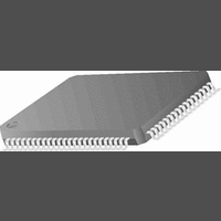
CR16MCS9VJE8 National Semiconductor, CR16MCS9VJE8 Datasheet - Page 7

CR16MCS9VJE8
Manufacturer Part Number
CR16MCS9VJE8
Description
16-Bit Microcontroller IC
Manufacturer
National Semiconductor
Datasheet
1.CR16MCS9VJE8.pdf
(156 pages)
Specifications of CR16MCS9VJE8
Controller Family/series
CR16X
Core Size
16 Bit
Program Memory Size
64K X 8 Flash
Digital Ic Case Style
PQFP
No. Of Pins
80
Mounting Type
Surface Mount
Clock Frequency
25MHz
Lead Free Status / RoHS Status
Contains lead / RoHS non-compliant
Available stocks
Company
Part Number
Manufacturer
Quantity
Price
Company:
Part Number:
CR16MCS9VJE8
Manufacturer:
ON
Quantity:
8 917
Company:
Part Number:
CR16MCS9VJE8-CBB
Manufacturer:
ON
Quantity:
846
Company:
Part Number:
CR16MCS9VJE8-CBC
Manufacturer:
ON
Quantity:
109
Company:
Part Number:
CR16MCS9VJE8-CBD
Manufacturer:
ON
Quantity:
17
Company:
Part Number:
CR16MCS9VJE8-CBE
Manufacturer:
ON
Quantity:
1 950
The MICROWIRE interface allows several devices to com-
municate over a single system consisting of four wires: serial
in, serial out, shift clock, and slave enable. At any given time,
the MICROWIRE interface operates as the master or a slave.
The support supports the full set of slave select for multi-
slave implementation.
In master mode, the shift clock is generated on chip under
software control. In slave mode, a wake-up out of power-
save mode is triggered via the Multi-Input Wake-Up module.
3.14
The CR16CAN device contains a FullCAN class, CAN serial
bus interface for applications that require a high speed (up to
1MBits per second) or a low speed interface with CAN bus
master capability. The data transfer between CAN and the
CPU is established by 15 memory mapped message buffers,
which can be individually configured as receive or transmit
buffers. An incoming message is filtered by two masks, one
for the first 14 message buffers and another one for the 15th
message buffer to provide a basic CAN path. A priority de-
coder allows any buffer to have the highest or lowest transmit
priority. Remote transmission requests can be processed au-
tomatically by automatic reconfiguration to a receiver after
transmission or by automated transmit scheduling upon re-
ception. In addition, a time stamp counter (16-bits wide) is
provided to support real time applications.
The CR16CAN device is a fast core bus peripheral, which al-
lows single cycle byte or word read/write access. A set of di-
agnostic features (such as loopback, listen only, and error
identification) support the development with the CR16CAN
module and provide a sophisticated error management tool.
The CR16CAN receiver can trigger a wake-up condition out
of the power-save modes via the Multi-Input Wake-Up mod-
ule.
3.15
The ACCESS.bus interface module (ACB) is a two-wire seri-
al interface with the ACCESS.bus physical layer. It is also
compatible with Intel’s System Management Bus (SMBus)
and Philips’ I
a bus master or slave, and can maintain bi-directional com-
munications with both multiple master and slave devices.
The ACCESS.bus receiver can trigger a wake-up condition
out of the power-save modes via the Multi-Input Wake-Up
module.
3.16
The A/D Converter (ADC) module is a 12-channel multi-
plexed-input analog-to-digital converter. The A/D Converter
receives an analog voltage signal on an input pin and con-
verts the analog signal into an 8-bit digital value using suc-
cessive approximation. The CPU can then read the result
from a memory-mapped register. The module supports four
automated operating modes, providing single-channel or 4-
channel operation in single or continuous mode.
The device has a separate pin, Vref, for the A/D reference
voltage.
CR16CAN
ACCESS.BUS INTERFACE
A/D CONVERTER
2
C bus. The ACB module can be configured as
7
3.17
The Dual Analog Comparator (ACMP2) module contains two
independent analog comparators with all necessary control
logic. Each comparator unit compares the analog input volt-
ages applied to two input pins and determines which voltage
is higher. The CPU uses a memory-mapped register to con-
trol the comparator and to obtain the comparison results. The
comparison result can also be applied to comparator output
pins.
3.18
A powerful cross-development tool set is available from Na-
tional Semiconductor and third parties to support the devel-
opment and debugging of application software for the
CR16MCS9. The tool set lets you program the application
software in C and is designed to take full advantage of the
CompactRISC architecture.
There are In-System Emulation (ISE) devices available for
the device from iSYSTEM™, as well as lower-cost evaluation
boards. See your National Semiconductor sales representa-
tive for current information on availability and features of em-
ulation equipment and evaluation boards.
ANALOG COMPARATORS
DEVELOPMENT SUPPORT
www.national.com


