QDE-825D BANNER ENGINEERING, QDE-825D Datasheet - Page 34
QDE-825D
Manufacturer Part Number
QDE-825D
Description
Safety Light Curtain
Manufacturer
BANNER ENGINEERING
Datasheet
1.QDE-815D.pdf
(74 pages)
Specifications of QDE-825D
Light Curtain Type
Safety
Accessory Type
Machine Interface Cable
For Use With
EZ-Screen Safety Light Screen


32
32
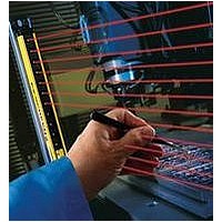
Figure 3-12. Corner mirror alignment
Figure 3-13. Optical alignment using the LAT-1
Reduced Resolution allows objects of a certain maximum size to
interrupt the defined area without causing a Trip condition (i.e.,
the OSSDs turn OFF). Use Reduced Resolution only when
necessary. In Reduced Resolution applications, the separation
distance always increases due to the larger depth penetration
factor (Dpf). In either case see Section 3.1.1 to determine
separation distance.
With 2-beam Reduced Resolution enabled, any two
consecutive beams, (except for the sync beam), can be
blocked without causing a stop condition. Thus, multiple “holes”
are created in which 14 mm systems will “see” a 30 mm object
and ignore an 8.5 mm object. Similarily, 30 mm systems will
“see” a 60 mm object and ignore a 17 mm object. See Figure
4-1 for DIP-switch configuration. During operation, the Status
indicator flashes Green when Reduced Resolution is enabled.
3.4.2 Reduced Resolution (Floating Blanking)
P/N 133487
P/N 112852 rev. F
Installation and Alignment
Overview
Component #1
(Emitter)
Component #2
Component #4
(Receiver)
(Mirror)
Component #3
(Mirror)
One or multiple areas within an EZ-SCREEN sensor pair may
be blanked out. The minimum number of beams between two
blanked areas is one. Any beam other than the sync beam may
be blanked. All beams of a fixed blanked area must stay blocked
at all times (after the fixed blanking configuration mode has been
exited), in order for the OSSDs to stay ON.
Fixed Blanking Configuration Procedure
3.4.3 Fixed Blanking
14 mm
Resolution
30 mm
Resolution
1. From normal operation or a power OFF condition, move the
2. Move the fourth and fifth DIP switches (the second RR and
3. The receiver should now either be in a lockout condition or
4. If power is OFF: Apply power
5. Fixed Blanking configuration indicated by:
6. Position object(s) to be blanked.
7. When beams are blocked, the 7-segment display alternates
Use Reduced Resolution and Fixed Blanking only when
necessary. Any holes created in the defined area either must be
completely filled by the blanked object or the separation distance
must be increased to account for the larger resolution (see Section
3.1.1).
Model
second and third DIP switches (the first RR and T/L) both to
the left (T and RR position). See Figure 3-14.
T/L) both to the right (L and OFF position).
power is still OFF.
Lockout condition: Perform a valid reset sequence (close
the reset switch for 0.25 to 2 seconds, then reopen the
switch).
• Display alternates between “PFA” and the number of
• Zone indicators active
• Yellow Reset indicator OFF
• Status indicator ON Red
between “PFA” and the number of blocked beams. The
zone indicators remain active and denote the location of
blocked beams.
blocked beams (“0” if all beams are clear).
(PFA = Program Fixed Blanking Active)
WARNING . . .
and Fixed Blanking
OFF
ON (2-beam)
OFF
ON (2-beam)
Resolution
Reduced
Setting
Banner Engineering Corp.
Banner Engineering Corp.
www.bannerengineering.com • Tel: 763.544.3164
www.bannerengineering.com • Tel: 763.544.3164
Use of Reduced Resolution
(Not applicable)
8.5 mm (0.34")
(Not applicable)
17 mm (0.67")
Maximum Size
of Undetected
Objects
Instruction Manual
•
•
Minneapolis, U.S.A.
Minneapolis, U.S.A.
14 mm (0.55")
30 mm (1.18")
30 mm (1.18")
60 mm (2.36")
Resolution
EZ-SCREEN
Resulting
Related parts for QDE-825D
Image
Part Number
Description
Manufacturer
Datasheet
Request
R

Part Number:
Description:
CDS EU 8 F RT 30 DSF8X22 1 GN B 30.0 63.5 12.7 5.46 N
Manufacturer:
BANNER ENGINEERING
Part Number:
Description:
CDS EU 8 F RT 5.0 DSF8x22 1 GN B 5.00 63.5 12.7 5.46 N
Manufacturer:
BANNER ENGINEERING
Part Number:
Description:
CDS EU 8 F RT 8.0 DSF8x22 1 GN B 8.00 63.5 12.7 5.46 N
Manufacturer:
BANNER ENGINEERING
Part Number:
Description:
CDS EU 8 F ST 15
Manufacturer:
BANNER ENGINEERING
Datasheet:
Part Number:
Description:
CDS EU 8 F RT 15 DSF8x22 1 GN B 15.0 63.5 12.7 5.46 N
Manufacturer:
BANNER ENGINEERING
Part Number:
Description:
CDS EU 8 F RT 23 DSF8X22 1 GN B 23.0 63.5 12.7 5.46 N
Manufacturer:
BANNER ENGINEERING

Part Number:
Description:
Safety Light Curtain
Manufacturer:
BANNER ENGINEERING
Datasheet:

Part Number:
Description:
Photoelectric Sensor
Manufacturer:
BANNER ENGINEERING
Datasheet:

Part Number:
Description:
Programmable Indicator Light
Manufacturer:
BANNER ENGINEERING
Datasheet:
Part Number:
Description:
INDICATOR LED PANEL 50MM GRN/RED/YEL 30V
Manufacturer:
BANNER ENGINEERING
Datasheet:
Part Number:
Description:
Programmable Indicator Light
Manufacturer:
BANNER ENGINEERING
Datasheet: