QDE-825D BANNER ENGINEERING, QDE-825D Datasheet - Page 35
QDE-825D
Manufacturer Part Number
QDE-825D
Description
Safety Light Curtain
Manufacturer
BANNER ENGINEERING
Datasheet
1.QDE-815D.pdf
(74 pages)
Specifications of QDE-825D
Light Curtain Type
Safety
Accessory Type
Machine Interface Cable
For Use With
EZ-Screen Safety Light Screen


EZ-SCREEN
Instruction Manual
• Display: PFC ON solid (PFC = Program Fixed Blanking
• Zone indicators flash approximate location of fixed
• Reset indicator single-flashing Yellow
• Status indicator single-flashing Red
Figure 3-14. DIP switch configuration to teach fixed blanking
Cascaded systems: To test a cascaded system, each light
screen must be tested individually, while monitoring the status
indicator on the first receiver in the cascade.
After optimizing the optical alignment and configuring fixed
blanking and Reduced Resolution (if applicable), perform the
trip test to verify the detection capability of the EZ-SCREEN
System. This test will also verify correct sensor orientation
(Section 3.1.5), identify optical short circuits (Section 3.1.6), and
verify the expected resolution for applications using Reduced
Resolution (Section 3.4.2). Once the installation has passed
the trip test, the safety outputs may be connected and the
commissioning checkout may be performed (initial installations
only).
10. Perform a valid reset sequence (see Step 4) or cycle power.
11. To disable fixed blanking, follow this same procedure, but
With Power ON:
1. Position object(s) in the defined area.
2. Set RR and T/L switches as shown (do
3. Press the Reset button or cycle power.
4. Reconfigure DIP switches for normal
5. Press the Rest button or cycle power.
NO TE: If the EDM wiring does not match the
OFF
ON (2-beam)
8. To teach the blanked beams, simply re-configure DIP
9. Receiver indicates:
3.4.4 Trip Test
Banner Engineering Corp.
Banner Engineering Corp.
not change SC2/SC1 or E1/E2 switch
positions).
operation.
www.bannerengineering.com • Tel: 763.544.3164
www.bannerengineering.com • Tel: 763.544.3164
switch position shown (E2), an EDM error
occurs and fixed blanking or cascade
configuration will not be allowed.
Resolution
switches for normal operation (see Figure 4-1). Verify that
only the objects to be blanked are interrupting the defined
area. A lockout will occur if an object is moved or removed
after teaching.
remove all objects not to be blanked at Step 6.
Reduced
Complete)
blanked area programmed
Appropriate Test Pieces for Trip Test
14 mm Resolution
14 mm (0.55") dia.
Model STP-13
30 mm (1.18") dia.
Model STP-14
•
•
Minneapolis, U.S.A.
Minneapolis, U.S.A.
Models
30 mm Resolution
30 mm (1.18") dia.
Model STP-14
60 mm (2.36") dia.
Model STP-15
Models
1. Select the proper test piece (see table above), supplied with
2. Verify that the EZ-SCREEN is in RUN mode with the Green
3. Pass the specified test piece through the defined area in
4. During each pass, while the test piece is interrupting the
• Latch Output Operation: The Status indicator must turn
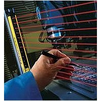
Figure 3-15. EZ-SCREEN trip test
Emitter
the receiver.
Status indicator ON (or flashing if Reduced Resolution is
enabled), all Zone indicators are Green, and the Yellow
Status indicator ON. A manual reset may be required in Latch
mode (see Sections 4.2 and 4.3).
three paths: near the emitter, near the receiver, and midway
between the emitter and receiver (Figure 3-15).
defined area, at least one Zone indicator must be Red. The
Red Zone indicator must change with the position of the
test piece within the defined area.
• T rip Output Operation: The Status indicator must turn Red
and remain Red for as long as the test piece remains in the
defined area. If not, the installation has failed the trip test.
Red and remain Red. The Yellow Reset indicator must
remain ON steady. If the Reset indicator begins to flash
at any time while the test piece is interrupting the defined
area, the installation has failed the trip test.
Emitter
Trip Test with Corner Mirror
Installation and Alignment
Test Piece
Mirror #1
Receiver
Overview
Receiver
P/N 112852 rev. F
P/N 133487
33
33
Related parts for QDE-825D
Image
Part Number
Description
Manufacturer
Datasheet
Request
R

Part Number:
Description:
CDS EU 8 F RT 30 DSF8X22 1 GN B 30.0 63.5 12.7 5.46 N
Manufacturer:
BANNER ENGINEERING
Part Number:
Description:
CDS EU 8 F RT 5.0 DSF8x22 1 GN B 5.00 63.5 12.7 5.46 N
Manufacturer:
BANNER ENGINEERING
Part Number:
Description:
CDS EU 8 F RT 8.0 DSF8x22 1 GN B 8.00 63.5 12.7 5.46 N
Manufacturer:
BANNER ENGINEERING
Part Number:
Description:
CDS EU 8 F ST 15
Manufacturer:
BANNER ENGINEERING
Datasheet:
Part Number:
Description:
CDS EU 8 F RT 15 DSF8x22 1 GN B 15.0 63.5 12.7 5.46 N
Manufacturer:
BANNER ENGINEERING
Part Number:
Description:
CDS EU 8 F RT 23 DSF8X22 1 GN B 23.0 63.5 12.7 5.46 N
Manufacturer:
BANNER ENGINEERING

Part Number:
Description:
Safety Light Curtain
Manufacturer:
BANNER ENGINEERING
Datasheet:

Part Number:
Description:
Photoelectric Sensor
Manufacturer:
BANNER ENGINEERING
Datasheet:

Part Number:
Description:
Programmable Indicator Light
Manufacturer:
BANNER ENGINEERING
Datasheet:
Part Number:
Description:
INDICATOR LED PANEL 50MM GRN/RED/YEL 30V
Manufacturer:
BANNER ENGINEERING
Datasheet:
Part Number:
Description:
Programmable Indicator Light
Manufacturer:
BANNER ENGINEERING
Datasheet: