NT2S-SF127B-E Omron, NT2S-SF127B-E Datasheet
NT2S-SF127B-E
Specifications of NT2S-SF127B-E


Related parts for NT2S-SF127B-E


NT2S-SF127B-E Summary of contents
Page 1
Cat. No. V03E-EN-01 NTXS Programmable Terminals USER´S MANUAL ...
Page 2
User’s Manual for NTXS i ...
Page 3
... Thank you for purchasing NTXS Series product from Omron. NTXS Series Products are versatile operator interfaces with Microsoft Windows® based configuration Software. This manual will help you to safely install, configure and operate NTXS Products. All the safety warnings and precautions must be followed to ensure proper unit performance and personal safety ...
Page 4
Introduction 1.1 Purpose of this Manual 1.2 Introduction to NTXS 1.3 How NTXS Works 1.4 NTXS Series Specifications 2. Hardware 2.1 Installation Instructions 2.2 Power Requirements 2.3 Communication Ports 3. Getting Started 3.1 Introduction 3.2 Application - Tags, Screens, ...
Page 5
Diagnostics and Maintenance 8.1 Diagnostics 8.2 Maintenance Appendix A Cable Diagrams ...
Page 6
INTRODUCTION In this Chapter Purpose of this Manual Introduction to NTXS How NTXS works NTXS Specifications Page 1 ...
Page 7
... This document is based on information available at the time of its publication. While efforts have been made to be accurate, the information in this document may not cover all the details or variations in hardware or software. Features described herein may not be present in all hardware. Omron reserves the right to update information in this publication without prior notice. ...
Page 8
How NTXS Works The NTXS follows a specific sequence for performing the tasks defined by the user in the application. The sequence is as shown below START Power-up Message Power up Task A IBM Y Complete IBM Comm Communication ...
Page 9
B Valid N Screen F password ? Y D Perform Before Showing Task List for new Screen C Upload Tag Block Upload Alarm Block Serv Alarm Display Screen Display Associated Screens Serv While Showing Task Check if same key pressed ...
Page 10
I New N key A Pressed ? Y Password N G Protected Key ? Y Valid Key N A Password ? Y G Serv Key Press Task A Page 5 ...
Page 11
... NT2S-SF121B-EV2 24VDC on Power Port RS232 / CMOS NT2S-SF122B-EV2 5VDC on PLC port NT2S-SF123B-EV2 5VDC on PLC port NT2S-SF125B-E 24VDC on Power Port RS232 / CMOS NT2S-SF126B-E 5VDC on PLC port NT2S-SF127B-E 5VDC on PLC port NT3S-ST121B-E 24VDC on Power Port RS485 / RS232 / CMOS NT3S-ST123B-E 24VDC on Power Port RS485 / RS232 / CMOS NT3S-ST124B-E ...
Page 12
... NT2S-SF121B-EV2 Specifications: Power: 24VDC + 10%, 1.5 W maximum Display: 2 lines of 16 characters Backlit LCD. Bezel: IP65 rated . Keys: 6 User definable keys with tactile feedback. LEDs: 2 LEDs. Memory: 24Kbytes Application Memory Communication: One RS232/CMOS port for connecting to PLC and one RS232 port for Programming and Printing ...
Page 13
... NT2S-SF122B-EV2 Specifications: Power: +5VDC + 10% from PLC Display: 2 lines of 16 characters Backlit LCD. Bezel: IP65 rated . Keys: 6 User definable keys with tactile feedback. LEDs: 2 LEDs. Memory: 24Kbytes Application Memory Communication: One RS232/CMOS port for connecting to PLC and one RS232 port for Programming and Printing ...
Page 14
... NT2S-SF123B-EV2 Specifications: Power: +5VDC + 10% from PLC Display: 2 lines of 16 characters Backlit LCD. Bezel: IP65 rated . Keys: 6 keys with tactile feedback. LEDs: 2 LEDs. Communication: One CMOS port for connecting to PLC Temperature Humidity: 10% to 90% (Non condensing) Immunity to ESD: Level 3 as per IEC1000-4-2 Immunity to Transients: Level 3 as per IEC1000-4-4 ...
Page 15
... NT2S-SF125B +/- F4 F8 CLR 0 Specifications: Power: 24VDC + 10%, 1.5 W maximum Display: 2 lines of 16 characters Backlit LCD. Bezel: IP65 rated . Keys: 20 User definable keys with tactile feedback. Memory: 24Kbytes Application Memory Communication: One RS232/CMOS port for connecting to PLC and one RS232 port for Programming and Printing ...
Page 16
... NT2S-SF126B +/- F4 F8 CLR 0 Specifications: Power: +5VDC + 10% from PLC Display: 2 lines of 16 characters Backlit LCD. Bezel: IP65 rated . Keys: 20 User definable keys with tactile feedback. Memory: 24Kbytes Application Memory Communication: One RS232/CMOS port for connecting to PLC and one RS232 port for Programming and Printing ...
Page 17
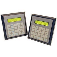
... NT2S-SF127B-E F1 REG DATA +/- F4 CLR 0 Specifications: Power: +5VDC + 10% from PLC Display: 2 lines of 16 characters Backlit LCD. Bezel: IP65 rated . Keys: 20 keys with tactile feedback. Communication: One CMOS port for connecting to PLC Temperature Humidity: 10% to 90% (Non condensing) Immunity to ESD: Level 3 as per IEC1000-4-2 ...
Page 18
NT3S-ST121B-E Specifications: Power: +24VDC + 10%, 3.5W maximum Display: 192 x 64 Pixels Monochrome Graphical Backlit LCD Bezel: IP65 rated. Touch Screen: 4 wire, Analog resistive Touch Screen Memory: 120Kbytes Application Memory. Communication: Two RS232/RS485/CMOS ports for connecting to PLC, ...
Page 19
NT3S-ST123B-E Specifications: Power: +24VDC + 10%, 3.5W maximum Display: 192 x 64 Pixels Monochrome Graphical Backlit LCD Bezel: IP65 rated. Touch Screen: 4 wire, Analog resistive Touch Screen Memory: 120Kbytes Application Memory. Communication: One RS232/RS485/CMOS and one RS232/CMOS port for ...
Page 20
NT3S-ST124B-E Specifications: Power: +24VDC + 10%, 3.5W maximum Display: 192 x 64 Pixels Monochrome Graphical Backlit LCD Bezel: IP65 rated. Touch Screen: 4 wire, Analog resistive Touch Screen Memory: 120Kbytes Application Memory. Communication: One RS232/RS485/CMOS and one RS232/CMOS port for ...
Page 21
NT3S-ST126B-E Specifications: Power: +24VDC + 10%, 3.5W maximum Display: 192 x 64 Pixels Monochrome Graphical Backlit LCD Bezel: IP65 rated. Touch Screen: 4 wire, Analog resistive Touch Screen Memory: 120Kbytes Application Memory. Communication: Two RS232/CMOS ports for connecting to PLC, ...
Page 22
HARDWARE In this Chapter Installation Instructions Power Requirements Serial Port PLC Port Page 17 ...
Page 23
Installation Instructions NTXS series units should be mounted on a panel. Gasket and mounting clamps are provided with each NTXS unit for proper mounting. Environmental Considerations: Make sure that the unit is installed correctly and that the environmental operating ...
Page 24
... NT2S-SF121B-EV2, NT2S-SF122B-EV2, NT2S-SF123B-EV2 Panel Cutout: 92. 45.00 mm (1/8 DIN size) All dimensions are in mm. 108.30 91.20 NT2S-SF125B-E, NT2S-SF126B-E, NT2S-SF127B-E Panel cutout: 92. 92.00 mm (1/4 DIN size) All dimensions are in mm. 2-4 91.30 106.88 NT3S-ST121B-E, NT3S-ST123B-E, NT3S-ST124B-E, NT3S-ST126B-E Panel cutout: 132. 69.00 mm All dimensions are in mm. ...
Page 25
... PLC port NT2S-SF123B-EV2 +5VDC + 10% on PLC port NT2S-SF125B-E +24VDC + 10%, 1.5W maximum on Power Port NT2S-SF126B-E +5VDC + 10% on PLC port NT2S-SF127B-E +5VDC + 10% on PLC port NT3S-ST121B-E +24VDC + 10%, 3.5W maximum on Power Port NT3S-ST123B-E +24VDC + 10%, 3.5W maximum on Power Port NT3S-ST124B-E +24VDC + 10%, 3.5W maximum on Power Port NT3S-ST126B-E +24VDC + 10%, 3 ...
Page 26
... Communication Ports NTXS models have two communication Ports. One port of NT2S models has RS232/CMOS signals. This port is used to connect to PLC. The other port has RS232 signals and this port is used for receiving configuration setup and printing. NT3S has Multi-Signal ports meaning RS232/RS485/CMOS signal level ports. NT3S units can simultaneously communicate with two devices on these serial ports ...
Page 27
NT3S-ST121B-E Com1 and Com2 Ports Port Type: DB9 Female Pin Name Number 1 TX+ 2 232TXD 3 RXD 4 RX+ 5 GND 6 VCC 7 CMOSTXD 8 TX- 9 RX- NT3S-ST123B-E / ST124B-E Com1 Port Port Type: DB9 Female Pin ...
Page 28
... Com1 Port (PLC Port) Port Type: DB9 Female Pin Name Number 1 GND 2 232TXD 3 RXD 4 GND 5 GND 6 VCC 7 CMOSTXD 8 DIR 9 PLC ATTACH NT2S-SF122B-E / SF126B-E Com1 Port (PLC Port) Port Type: DB9 Male Pin Name Number DIR 3 232TXD 4 VCC 5 GND 6 CMOSTXD 7 RXD 8 RXD 9 ...
Page 29
... NT2S-SF121B-E / SF122B-E / SF125B-E / SF126B-E Com2 Port (Serial Port) Port Type: DB9 Female Pin Name Number TXD 3 RXD GND NT2S-SF123B-E / SF127B-E Com1 Port (PLC Port) Port Type: DB9 Male Pin Name Number VCC 5 GND 6 CMOS TXD 7 RXD 8 RXD 9 NC Description NC Transmit RS232 ...
Page 30
GETTING STARTED In this Chapter Introduction Application - Tags, Screens, Keys and Tasks PLC Communications Page 25 ...
Page 31
... Once the application is defined, firmware for the specific unit and PLC is downloaded and then application is downloaded into the unit. NTXS can now communicate with a PLC. To download application / firmware, connect appropriate programming cable to Serial port of NT2S models. Setup can be downloaded on any one of the ports of NT3S models. ...
Page 32
... NT3S-ST126B Important note: For the NT3S models the old version cables: NT2S-CN212, NT2S-CN215 and NT2S-CN223-V1, cannot be used. For the NT2S models they can still be used. Please refer to the Appendix “Cable diagrams” for making your own cables between NTXS and serial ports of Omron plc’ ...
Page 33
UNDERSTANDING NTXS FEATURES In this Chapter Tasks Screens Keys / Touch-Screen Keys Alarms Application Task-List Page 28 ...
Page 34
This chapter explains in detail all the features of NTXS series. We recommend that you study this chapter before attempting to configure and use the NTXS . 4.1 Tasks The task-list forms the back bone of NTXS. A task can ...
Page 35
Understanding NTXS Features Complete list of tasks supported is as follows: 1. Goto Screen User can select the screen to be displayed from a list of defined screens. 2. Goto Next Screen This task is useful when two screens are ...
Page 36
... PLC tag can be copied to STR. 17. Copy Tag to LED Some NTXS units have LED’s on the Keypad. LED’s on the keypad of NT2S can be turned on/off depending on the value of a tag. The tag should be copied to LED register and the LEDs will display the tag value. ...
Page 37
Understanding NTXS Features iv) Switch to next data entry: Accepts the current data entered and data entry focus is switched to next data entry field. v) Increase value by 1: Value of the data entry variable is increased by 1. ...
Page 38
Numeric key B: Data at current location is entered as B using this task. This task is specially used for hex data entry. xxv) Numeric key C: Data at current location is entered as C using this task.This task ...
Page 39
Understanding NTXS Features User should know some Screen basics while working with screens. 1. Number: Each screen must have a unique Screen Number. Please refer to following table for details on Screen number: Base Screen Popup Screen 2. Name User ...
Page 40
... If one port is defined as Native serial driver, this port can not be used as a PLC port. If none of the ports are defined as Printer ports, serial printing will not be done. For NT2S models, data is printed on the serial port. Communication settings for serial printing can be set from NTXS settings window. ...
Page 41
Understanding NTXS Features 1. Press key with definition ‘Accept Data Entry’ (generally key legend is ENT) to initiate data entry mode. Data entry mode is indicated by flashing the complete coil data entry object. 2. Use keys with definition ‘Increase ...
Page 42
This object is only available in NT3S models. 12. Round Rectangle: User can draw a rectangle with rounded corners of required size and required color using this object. User can also fill the round rectangle ...
Page 43
... Keys / Touch screen keys NT2S models have keypads whereas NT3S models have touchpanels for user input. User can define keys as per the application requirement. NT-XS software enables user to define key tasks. Most of the tasks men- tioned in the task list are supported as keys tasks. ...
Page 44
To display alarms user must follow steps given below: 1. Define consecutive or discrete alarms from ‘Define Alarm’ window. Definition contains the alarm text and print selection Screen Definition, place Alarm object on the appropriate location. Alarms will ...
Page 45
CONFIGURATION SOFTWARE In this Chapter Introduction to NT-XS Software Installing NT-XS Software NT-XS Software - Basics Create a New Application Save and Download Application Page 40 ...
Page 46
... Download Firmware i.e. driver for the PLC. NTXS unit requires a PLC driver to communicate with the PLC. 5. Download application. 6. Now connect to the PLC with the correct PLC cable. *NT2S-SF123B-EV2 and NT2S-SF127B-E models do not require any setup. PLC should be programmed to work with these models 5.2 Installing NT-XS Software System requirements for installing NT-XS on your PC: Windows Version ...
Page 47
... The complete configuration is stored as an Application. This application is downloaded in NTXS . 5.3.1. NTXS Settings: This menu allows user to edit settings. For NT2S models, user can edit Printer port options. For NT3S models, user can edit only language option. Printer port options for NT3S will be selected in Network Configuration. ...
Page 48
NT-XS Menu Structure After starting up the NTXS software the following splash screen will be displayed. Main window will be displayed after the splash screen. Main window consists of two main parts: Menu Bar and the Tool Station. Configuration ...
Page 49
Configuration Software Menu bar operates like any standard Windows Menu bar. Click with mouse or use keys in combination with ALT key just like any other standard Windows based software. When no application is open above Menu bar will be ...
Page 50
Define Menu This menu defines the application. In the main window of NT-XS software, bottom line of the icons is dedi- cated for this menu. NTXS Settings - Defines NTXS settings. Network Configuration - Defines PLC node, node ID etc. ...
Page 51
Configuration Software Communicate Menu Communicate Menu Downloads / uploads application to / from NTXS . Communication Port - Sets COM port for communicating with NTXS . Download - Downloads Application to NTXS . Upload - Uploads Application from NTXS . ...
Page 52
Help Menu Help Menu, as the name suggests, offers help for the user application. Index - Lists all the Help topics About NT-XS - Displays the software version number. Configuration Software Page 47 ...
Page 53
Configuration Software 5.4 Create New Application Select New from File menu or click on the New Application button. In the dialog presented, select NTXS model and press OK. When Ok button is pressed, a dialogue box will be presented which ...
Page 54
... NTXS Settings from Define menu or Press F3 key or click on the NTXS Settings button. It may not always be necessary to change these settings. In NTXS Settings dialog box, printer port settings, Max characters per screen for serial printing for NT2S. For NT3S select number of languages. Press Select PLC to be used in the system ...
Page 55
... For NT3S models following window will be displayed. Select any required PLC on one port, set port settings and press Add a Node button. Repeat steps to add second PLC. Press Close button to close the window. For NT2S models following window will be displayed. Node button. Now select PLC and PLC Model. Assign a Node Address for the node Press OK to accept the selections made and close the window ...
Page 56
Select Tag Database.. from Define menu or Press F5 key or click on the Tags button. In Tags dialog box select the Node, Tag type, Register, enter Tag name and finally select number of bytes for the Tag. Press Add ...
Page 57
Configuration Software New Screen dialog box will appear. In New Screen dialog box, enter the Screen number, Screen Name and Screen description information. This is for programmers reference only. This information is NOT displayed on the actual NTXS Screen. Associated ...
Page 58
... A block cursor will blink at the location inside the text outline. Now enter text. The last character will be overwritten If the INSERT Mode (Computer Keyboard) is disabled, else new character will not be accepted. Font sizes can not be selected for NT2S models. Coil Data Entry Object: Click on the Data Entry button mouse pointer at desired location on the screen and click the left mouse button ...
Page 59
Configuration Software Register Data Entry Object: To edit a register in the PLC or the unit itself, select Register Data Entry in the Data entry dialog box. Register Data Entry dialog box allows user to select the tag, Data type, ...
Page 60
To display value of a word tag, select Register Value type in Display NTXS or PLC Data window. The window will now change to display Register options. Select the register to be displayed. Select the Data type and Format to ...
Page 61
Configuration Software Display Time Object: Time can be displayed on the NTXS display by placing a Display Time object. To display the object, click on the Time button . Place Time Object on the screen. To edit the format double ...
Page 62
Display Alarm Object: An Alarm object displays an alarm immediately after an alarm is triggered. Alarm text is defined in the Alarms dialog box. To place an Alarm object, click on the Alarms button by double clicking on the object ...
Page 63
Configuration Software Display Ellipse Object: User can draw ellipse on the NT3S display by using an Ellipse tool. To draw the object, click on the Ellipse button . Place on the screen, drag till required size is reached. To edit ...
Page 64
Bit Button Object: To draw the object on NT3S, click on the Bit Button icon window will enable user to select Button properties, General Attributes and Operation. Button Properties defines the properties of actual button object. General Attributes page is ...
Page 65
Configuration Software Word Button Object: To draw the object on NT3S, click on the Word Button icon window will enable user to select State properties, General Attributes. User can define different tasks de- pending on different states (ranges ...
Page 66
Bit Lamp Object: To draw the object on NT3S, click on the Bit Lamp button with three pages will be presented. Lamp properties page defines the display of the actual lamp. General attributes defines label properties and border enable / ...
Page 67
Configuration Software Word Lamp Object: To draw the object on NT3S, click on the Word Lamp button box with two pages will be presented. Tag, State Properties and General Attributes decide how the object will be displayed. State defines the ...
Page 68
Single Bargraph Object: To draw the object on NT3S, click on the Single Bargraph button User can select style to plot a bar for the specified word tag. Maximum and Minimum limits specify the range of the tag to be ...
Page 69
Configuration Software Multiple Bargraph Object: To draw the object on NT3S, click on the Multiple Bargraph button User can select number of bars, style and bar width. Individual bar properties sets Bar tag, Bar color, Maxi- mum and Minimum limits. ...
Page 70
Analog Meter Object: To draw the object on NT3S, click on the Analog Meter button wizard represents the word register on an analog meter. Dialog box has four pages: Meter Foreground properties, Meter Background properties, General attributes, Operation. Foreground Properties ...
Page 71
Configuration Software Numeric Keypad Object: To place Numeric keypad object on NT3S, click on the Numeric Keypad button the screen. This wizard helps user to edit data. Numeric keypad can be used on the screen which has a data entry ...
Page 72
Bitmap Object: To display a user defined bitmap on NT3S, click on the Bitmap button presented user can add a bitmap to library, delete a bitmap from the library or add a library bitmap to screen. User can add any ...
Page 73
Configuration Software Trend Object: To display the trend of any tag on NT3S, click on the Trend button location on the screen. In the dialog box presented user can select trending properties like Tag, Span time or Span Time Tag, ...
Page 74
Define Alarms Select Alarms.. from Define menu or Press F8 key or click on the Alarms button To add alarms, click ADD button. Select Tag to be monitored. Select the Alarm group. For first 16 alarms the group is ...
Page 75
Configuration Software Once all the screens are completely defined, user has to define the ‘Power-on Application Task’. Power- on Application Task is like a boot-up sequence for the unit. Tasks mentioned here are performed immediately after the unit is powered ...
Page 76
Save and Download Application Complete application has to be saved. Click ‘Save’ from ‘File’ main menu or press F2 key on the PC keyboard. A dialog box will be presented. Select required directory to save the application. Enter the ...
Page 77
... NTXS. From ‘Communicate’ menu, click ‘Download..’. In the download dialog box, check ‘Application’ radio-button. Press ‘OK’ button to download application to NTXS unit. Following window will be presented for NT2S models. Following window will be presented for NT3S models. After downloading the application also download the firmware by using the same method as described above but then selecting ‘ ...
Page 78
APPLICATIONS EXAMPLES In this Chapter Installations and Setup Define Node and Tags Define Screens Define Alarms Load Applications into NTXS Page 73 ...
Page 79
... Installations and Setup We will create a demo application for NT3S with Omron Host link PLC on Com1 and Native serial driver on Com2. We will increment a tag from the PLC. Display a bargraph using this tag. We will initialize the tag after the tag value = 500. ...
Page 80
... Select Omron Host Link Driver. Select communication parameters from Port settings. Default communication parameters are 9600, even Click Add a node to add the selected node. 5. Define tags from the PLC Tag database. Define D0 - NTXS Data Register. Select Omron Node. Define DM register DM0. Applications Examples ...
Page 81
Applications Examples 6. Now we will define the screens Screens. - Select Text object. Select Font size 7 x 14. Place the object in top left corner of the screen. Type “DM0=”. - Select Data entry object. Place ...
Page 82
Goto Screen task list. In before showing tasklist add task “Write Value to tag”. Write DM0 = 0. In while showing task, add task “Add a constant value to tag”. Add 1 to DM0 Add “Wait” task. Wait till ...
Page 83
Applications Examples 7. Now we will save the application. Click OK to save the application. 8. Now we will download the firmware to the unit. Click download application. A window will appear. Select Firmware. Set appropriate com port. Connect Power ...
Page 84
FREQUENTLY ASKED QUESTIONS In this Chapter How Page 79 ...
Page 85
... Any screen can be kept secret using the ‘Password’ feature for NTXS models. Password protected screen will not be displayed till the user enters the correct password. In case of NT2S Keys can be protected using the key password.Task for password protected key will not be performed till user enters the correct password ...
Page 86
DIAGNOSTICS AND MAINTENANCE In this Chapter Diagnostics Maintenance Page 81 ...
Page 87
... Diagnostics 8.1.1 Touch Screen Calibration Loss for NT3S: Touch screens are factory calibrated. Calibration is stored in a Flash memory. If user faces any of the following problems: - Any press inside defined object boundary results in three short beeps. - Undefined area performs a task of some other defined object. ...
Page 88
Maintenance 8.2.1 Clean all sides of the unit using a isopropyl alcohol solution. Use a clean, soft piece of cloth. Do not use a rough cloth as it may produce scratches on the unit. Take proper care while cleaning ...
Page 89
APPENDIX In this Chapter Cable Diagrams v ...
Page 90
... Appendix A Cable Diagrams Pin Configuration for Programming Cable for NT3S : Pin Configuration for Programming Cable for NT2S : Pin Configuration for communication cable between Omron plc RS232 port and NT3S: PC End NT3S End DB9 Female DB9 Male TXD RXD 3 3 RXD TXD ...
Page 91
... Pin Configuration for communication cable between Omron plc RS232 port and NT2S-SF121/SF125: Pin Configuration for communication cable between XtraDrive and NT3S: XtraDrive connector type (3M) - 10114-3000VE (connector) - 10314-52A0-008 (cover) Omron order code for XtraDrive connector: R7A-CNA01R PLC End NT2S End DB9 Male ...
Page 92
... Omron Europe B.V. Wegalaan 67-69 NL-2132 JD Hoofddorp The Netherlands Phone :(+31)23-5681300 Fax :(+31)23 5681388 Website: www.europe.omron.com i ...