NT2S-SF127B-E Omron, NT2S-SF127B-E Datasheet - Page 25
NT2S-SF127B-E
Manufacturer Part Number
NT2S-SF127B-E
Description
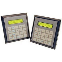
LCD Touch Panels 2x16LCD8FKEY+NMPAD MSSGDISP 5V
Manufacturer
Omron
Datasheets
1.NT2S-CN222-V1.pdf
(6 pages)
2.NT2S-SF127B-E.pdf
(92 pages)
3.NT3S-ST126B-E.pdf
(214 pages)
Specifications of NT2S-SF127B-E
External Width
107mm
Supply Voltage Max
5VDC
External Depth
26mm
Ip/nema Rating
IP65
Mounting Type
Panel
External Height
107mm
Approval Bodies
CULus, CE
Rohs Compliant
Yes
No. Of Characters
2 X 16
No. Of Keys
20
Operating Temperature Range
0°C To +50°C
For Use With
Micro PLCs
Lead Free Status / RoHS Status
Lead free / RoHS Compliant
Lead Free Status / RoHS Status
Lead free / RoHS Compliant


2.2
Supply voltage requirements for NTXS series models is as follows:
NT2S-SF121B-EV2
NT2S-SF122B-EV2
NT2S-SF123B-EV2
NT2S-SF125B-E
NT2S-SF126B-E
NT2S-SF127B-E
NT3S-ST121B-E
NT3S-ST123B-E
NT3S-ST124B-E
NT3S-ST126B-E
Power and communication wiring must be in accordance with Class I, Division 2 wiring methods (Article 501-
4 (b) of the National Electrical Code, NEPA 70) and in accordance with the authority having jurisdiction.
Please follow the instructions given below while making power supply connections for models:
Follow the wiring diagram on the sticker of the unit which shows terminals.
To make a connection strip about 7mm of insulation of the wire, turn the connector screw
counter-clock wise until the gap is wide open. Insert the wire all the way in and turn the screw
clockwise until it is tight.
Wire lengths should be minimum. Wires should run in pairs with a neutral or common paired with a
live or signal wire.
NTXS +24VDC model is fused internally with a self resetting 60V, 400mA fuse. It is recommended
that all input power lines be protected from product failure by a fuse or breaker.
Adequate strain relief must be provided for the power connector, to ensure that vibration does not
cause the power connector to be pulled out.
All the NTXS products are housed in a moulded ABS plastic case which eliminates any
electrical shock hazard. Hence Safety Earth is not required to be connected to the chassis of the
unit.
The DC ground is not directly coupled to Earth ground internally. The unit is designed to operate
properly whether or not the DC ground is connected to the Earth ground. We do recommend,
however, that if the DC ground has to be connected to the Earth ground, the Earth connection
Power Requirements
A.
B.
C.
+24VDC + 10%, 1.5W maximum on Power Port
+5VDC + 10% on PLC port
+5VDC + 10% on PLC port
+24VDC + 10%, 1.5W maximum on Power Port
+5VDC + 10% on PLC port
+5VDC + 10% on PLC port
+24VDC + 10%, 3.5W maximum on Power Port
+24VDC + 10%, 3.5W maximum on Power Port
+24VDC + 10%, 3.5W maximum on Power Port
+24VDC + 10%, 3.5W maximum on Power Port
“THIS EQUIPMENT IS SUITABLE FOR USE IN CLASS I, DIVISION 2,
GROUPS A, B, C AND D OR NONHAZARDOUS LOCATIONS ONLY.”
“WARNING - EXPLOSION HAZARD - SUBSTITUTION OF COMPONENTS
MAY IMPAIR SUITABILITY FOR CLASS I, DIVISION 2.”
“WARNING - EXPLOSION HAZARD - DO NOT DISCONNECT
EQUIPMENT UNLESS POWER HAS BEEN SWITCHED OFF OR AREA IS
KNOWN TO BE NONHAZARDOUS.”
Page 20
Related parts for NT2S-SF127B-E
Image
Part Number
Description
Manufacturer
Datasheet
Request
R

Part Number:
Description:
LCD Touch Panels 5M Toolbus Port Cbl l for NT2S
Manufacturer:
Omron
Datasheet:

Part Number:
Description:
LCD Display Panel
Manufacturer:
Omron
Datasheet:
Part Number:
Description:
LCD Display Panel
Manufacturer:
Omron
Datasheet:

Part Number:
Description:
PLC Interface Cable
Manufacturer:
Omron
Datasheet:
Part Number:
Description:
PLC Interface Cable
Manufacturer:
Omron
Datasheet:

Part Number:
Description:
LCD Touch Panels 2x16 LCD MESSAGE DISPLAY 5VDC
Manufacturer:
Omron
Datasheet:
Part Number:
Description:
LCD Touch Panels 2x16 LCD 6FKEY 5VDC
Manufacturer:
Omron
Datasheet:
Part Number:
Description:
LCD Touch Panels 2x16LCD 8FKEY+NUMPAD 5VDC
Manufacturer:
Omron
Datasheet:
Part Number:
Description:
LCD Touch Panels 2x16 LCD 6FKEY RTC 24VDC
Manufacturer:
Omron
Datasheet:
Part Number:
Description:
LCD Touch Panels 2x16LCD 8FKEY+NUMPAD RTC 24V
Manufacturer:
Omron
Datasheet:

Part Number:
Description:
LCD Touch Panels SF121 TO TOOLBUS PORT CBL 2M
Manufacturer:
Omron
Datasheet:
Part Number:
Description:
LCD Touch Panels SF122 TO TOOLBUS PORT CBL 2M
Manufacturer:
Omron
Datasheet:
Part Number:
Description:
LCD Touch Panels 9-Pin to PRPH PRT Cable 5M V2
Manufacturer:
Omron
Datasheet:

Part Number:
Description:
LCD Touch Panels 9 PIN TO PERIPH PORT CABLE 2M
Manufacturer:
Omron
Datasheet:
Part Number:
Description:
LCD Touch Panels 2M toolbus port cable for NT2
Manufacturer:
Omron
Datasheet: