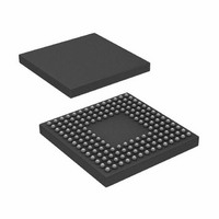
ADSP-BF531SBBC400 Analog Devices Inc, ADSP-BF531SBBC400 Datasheet - Page 7

ADSP-BF531SBBC400
Manufacturer Part Number
ADSP-BF531SBBC400
Description
IC,MICROPROCESSOR,32-BIT,CMOS,BGA,160PIN,PLASTIC
Manufacturer
Analog Devices Inc
Series
Blackfin®r
Type
Fixed Pointr
Datasheet
1.ADSP-BF531SBSTZ400.pdf
(12 pages)
Specifications of ADSP-BF531SBBC400
Rohs Status
RoHS non-compliant
Interface
SPI, SSP, UART
Clock Rate
400MHz
Non-volatile Memory
ROM (1 kB)
On-chip Ram
52kB
Voltage - I/o
1.8V, 2.5V, 3.3V
Voltage - Core
1.20V
Operating Temperature
-40°C ~ 85°C
Mounting Type
Surface Mount
Package / Case
160-CSPBGA
Device Core Size
16b
Architecture
Modified Harvard
Format
Fixed Point
Clock Freq (max)
400MHz
Mips
400
Device Input Clock Speed
400MHz
Operating Supply Voltage (typ)
1.2/1.8/2.5/3.3V
Operating Supply Voltage (min)
0.8/1.75V
Operating Supply Voltage (max)
1.32/3.6V
Operating Temp Range
-40C to 85C
Operating Temperature Classification
Industrial
Mounting
Surface Mount
Pin Count
160
Package Type
CSPBGA
Package
160CSP-BGA
Numeric And Arithmetic Format
Fixed-Point
Maximum Speed
400 MHz
Device Million Instructions Per Second
400 MIPS
For Use With
ADZS-BF533-EZLITE - KIT W/BOARD EVAL FOR ADSP-BF533
Lead Free Status / Rohs Status
Not Compliant
Available stocks
Company
Part Number
Manufacturer
Quantity
Price
Company:
Part Number:
ADSP-BF531SBBC400
Manufacturer:
ADI
Quantity:
329
Company:
Part Number:
ADSP-BF531SBBC400
Manufacturer:
Analog Devices Inc
Quantity:
10 000
Part Number:
ADSP-BF531SBBC400
Manufacturer:
ADI/亚德诺
Quantity:
20 000
Silicon Anomaly List
6.
05000158 - Instruction DMA Can Cause Data Cache Fills to Fail (Boot Implications):
DESCRIPTION:
After a DMA or core MMR DTEST register access has occurred to the L1 instruction memory, a data cache fill to the corresponding port
may get corrupted data. This situation can only occur if stalls are introduced because the core is accessing the same data memory bank as
the data cache fill.
This data cache fill can occur many cycles after the L1 Instruction memory DMA or MMR access. One example of the failure is when a
program that enables data cache is booted. The Instruction DMA that occurred during the boot may prime the processor to be
susceptible to data corruption in a data cache fill that occurs sometime during the main program's execution.
For Port A, data locations 0xFF80xxxx and instruction locations 0xFFA00000 -0xFFA07FFF (where applicable) are subject to the failure. For
Port B, data locations 0xFF90xxxx and instruction locations 0xFFA08000 - 0xFFA0FFFF (where applicable) are subject to the failure.
The problem will also occur if the last DMA transaction was to the L1 instruction memory while a low priority data cache fill is ongoing.
WORKAROUND:
The best workaround for this issue is to set bit 9 of any DCPLB Data register that you use. This bit is shown as a reserved bit in the
Hardware Reference Manual, but the documentation is being updated to describe the functionality of this bit.
A second workaround would be to perform a software core reset at the beginning of the program:
If the program will be performing both data caching and L1 Instruction Memory DMA, perform a Data DMA to the data SRAM which
shares a data port with the Instruction SRAM after performing an Instruction DMA. Do not perform any access that would cause data
caching or victimization from the time the Instruction DMA begins until after the Data DMA has completed. Also, an MMR DTEST access to
the corresponding data bank could also clear out the problem if the original problem was caused by the Instruction Memory DMA.
If the program will access the L1 Instruction Memory through the core MMR DTEST register, follow this access with a core MMR DTEST
register access to the corresponding Data Bank.
If the processor is either not DMAing to instruction memory or not using data cache, you will not encounter this problem.
The VisualDSP++ runtime libraries cache support functions contain a workaround for this anomaly where necessary.
APPLIES TO REVISION(S):
0.3, 0.4
P0.H = HI(SYSCR);
P0.L = LO(SYSCR);
R0.L = W[P0];
CC = BITTST(R0,4);
IF CC JUMP _No_Boot_Set;
BITSET(R0,4);
W[P0] = R0;
SSYNC;
RAISE 1;
_No_Boot_Set:
BITCLR(R0,4);
W[P0] = R0;
// Check System Reset Configuration Register
// Check NO BOOT ON SOFTWARE RESET Bit
// Set NO BOOT ON SOFTWARE RESET Bit
// Ensure write completes before executing RAISE
// Reset SYSCR to original value
NR003532D | Page 7 of 45 | July 2008
ADSP-BF531/BF532/BF533


