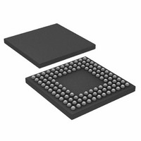
ADUC7122BBCZ-RL Analog Devices Inc, ADUC7122BBCZ-RL Datasheet - Page 46

ADUC7122BBCZ-RL
Manufacturer Part Number
ADUC7122BBCZ-RL
Description
PRECISION ANALOG MCU I.C
Manufacturer
Analog Devices Inc
Series
MicroConverter® ADuC7xxxr
Datasheet
1.ADUC7122BBCZ.pdf
(96 pages)
Specifications of ADUC7122BBCZ-RL
Core Processor
ARM7
Core Size
16/32-Bit
Speed
41.78MHz
Connectivity
I²C, SPI, UART/USART
Peripherals
POR, PWM, WDT
Number Of I /o
32
Program Memory Size
126KB (63K x 16)
Program Memory Type
FLASH
Ram Size
8K x 8
Voltage - Supply (vcc/vdd)
3 V ~ 3.6 V
Data Converters
A/D 13x12b, D/A 12x12b
Oscillator Type
Internal
Operating Temperature
-10°C ~ 95°C
Package / Case
108-LFBGA, CSPBGA
Lead Free Status / RoHS Status
Lead free / RoHS Compliant
Eeprom Size
-
Lead Free Status / RoHS Status
Lead free / RoHS Compliant
Other names
ADUC7122BBCZ-RL
ADUC7122BBCZ-RLTR
ADUC7122BBCZ-RLTR
Available stocks
Company
Part Number
Manufacturer
Quantity
Price
Company:
Part Number:
ADUC7122BBCZ-RL
Manufacturer:
Analog Devices Inc
Quantity:
10 000
ADuC7122
OSCILLATOR AND PLL—POWER CONTROL
The ADuC7122 integrates a 32.768 kHz oscillator, a clock
divider, and a PLL. The PLL locks onto a multiple (1275) of the
internal oscillator to provide a stable 41.78 MHz clock for the
system. The core can operate at this frequency or at binary
submultiples of it to allow power saving. The default core clock
is the PLL clock divided by 8 (CD = 3) or 5.2 MHz. The core
clock frequency can be output on the ECLK pin as described in
Figure 31. Note that when the ECLK pin is used to output the
core clock, the output signal is not buffered and is not suitable
for use as a clock source to an external device without an
external buffer.
A power-down mode is available on the ADuC7122.
The operating mode, clocking mode, and programmable clock
divider are controlled via two MMRs, PLLCON (see Table 75) and
POWCON (see Table 76). PLLCON controls the operating
mode of the clock system, and POWCON controls the core
clock frequency and the power-down mode.
NOTES
EXTERNAL CRYSTAL SELECTION
To switch to an external crystal, use the following procedure:
1.
2.
3.
4.
1. 32.768kHz ± 3%.
2. TO USE THE SECONDARY FUNCTION
3. WHEN THE SECONDARY FUNCTION
WATCHDOG
OF P1.4 AS XCLK, PLLCON BITS[1:0]
MUST EQUAL 11.
FOR P1.4 IS SET TO 2 (THAT IS, GP1CON[17:16] = 10),
THE ECLK FUNCTION IS SELECTED BY DEFAULT.
TIMERS
TIMER
Enable the Timer2 interrupt and configure it for a timeout
period of >120 μs.
Follow the write sequence to the PLLCON register, setting
the MDCLK bits to 01 and clearing the OSEL bit.
Force the part into nap mode by following the correct write
sequence to the POWCON register.
When the part is interrupted from nap mode by the Timer2
interrupt source, the clock source has switched to the
external clock.
CORE
OSCILLATOR
INT. 32kHz
Figure 31. Clocking System
OCLK 32.768kHz
PLL
I
2
C
1
CD
41.78MHz
UCLK
AT POWER-UP
OSCILLATOR
CRYSTAL
ECLK
/2
CD
HCLK
3
PERIPHERALS
MDCLK
ANALOG
XTALO
XTALI
XCLK
Rev. 0 | Page 46 of 96
2
Example Source Code
3)) //ensures timer value loaded
//enable T2 interrupt
// Set Core into Nap mode
In noisy environments, noise can couple to the external crystal
pins, and PLL may lose lock momentarily. A PLL interrupt is
provided in the interrupt controller. The core clock is immediately
halted, and this interrupt is serviced only when the lock is restored.
In case of crystal loss, the watchdog timer should be used. During
initialization, a test on the RSTSTA can determine if the reset
came from the watchdog timer.
EXTERNAL CLOCK SELECTION
To switch to an external clock on P1.4, configure P1.4 in
Mode 2. The external clock can be up to 41.78 MHz, providing
the tolerance is 1%.
Example Source Code
3)) //ensures timer value loaded
//enable T2 interrupt
T2LD = 5;
T2CON = 0x480;
while ((T2VAL == t2val_old) || (T2VAL >
IRQEN = 0x10;
PLLKEY1 = 0xAA;
PLLCON = 0x01;
PLLKEY2 = 0x55;
POWKEY1 = 0x01;
POWCON = 0x27;
POWKEY2 = 0xF4;
T2LD = 5;
TCON = 0x480;
while ((T2VAL == t2val_old) || (T2VAL >
IRQEN = 0x10;
PLLKEY1 = 0xAA;
PLLCON = 0x03; //Select external clock
PLLKEY2 = 0x55;
POWKEY1 = 0x01;
POWCON = 0x27; // Set Core into Nap mode
POWKEY2 = 0xF4;


