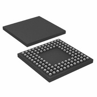
ADUC7122BBCZ-RL Analog Devices Inc, ADUC7122BBCZ-RL Datasheet - Page 63

ADUC7122BBCZ-RL
Manufacturer Part Number
ADUC7122BBCZ-RL
Description
PRECISION ANALOG MCU I.C
Manufacturer
Analog Devices Inc
Series
MicroConverter® ADuC7xxxr
Datasheet
1.ADUC7122BBCZ.pdf
(96 pages)
Specifications of ADUC7122BBCZ-RL
Core Processor
ARM7
Core Size
16/32-Bit
Speed
41.78MHz
Connectivity
I²C, SPI, UART/USART
Peripherals
POR, PWM, WDT
Number Of I /o
32
Program Memory Size
126KB (63K x 16)
Program Memory Type
FLASH
Ram Size
8K x 8
Voltage - Supply (vcc/vdd)
3 V ~ 3.6 V
Data Converters
A/D 13x12b, D/A 12x12b
Oscillator Type
Internal
Operating Temperature
-10°C ~ 95°C
Package / Case
108-LFBGA, CSPBGA
Lead Free Status / RoHS Status
Lead free / RoHS Compliant
Eeprom Size
-
Lead Free Status / RoHS Status
Lead free / RoHS Compliant
Other names
ADUC7122BBCZ-RL
ADUC7122BBCZ-RLTR
ADUC7122BBCZ-RLTR
Available stocks
Company
Part Number
Manufacturer
Quantity
Price
Company:
Part Number:
ADUC7122BBCZ-RL
Manufacturer:
Analog Devices Inc
Quantity:
10 000
I
Name:
Address:
Default Value:
Access:
Function:
I
Name:
Address:
Default Value:
Access:
Function:
Table 104. I2CxADR0 MMR in 7-Bit Address Mode (Address = 0xFFFF0898, 0xFFFF0918, Default Value = 0x00)
Bit
7:1
0
Table 105. I2CxADR0 MMR in 10-Bit Address Mode
Bit
7:3
2:1
0
Table 106. I2CxADR1 MMR in 10-Bit Address Mode
Bit
7:0
Table 107. I2CxDIV MMR
Bit
15:8
7:0
2
2
C Address 0 Register
C Address 1 Register
Name
I2CADR
R/W
Name
I2CMADR
R/W
Name
I2CLADR
Name
DIVH
DIVL
I2C0ADR0, I2C1ADR0
0xFFFF0898, 0xFFFF0918
0x00, 0x00
Read/write
This 8-bit MMR holds the 7-bit slave address +
the read/write bit when the master begins
communicating with a slave.
I2C0ADR1, I2C1ADR1
0xFFFF089C, 0xFFFF091C
0x00, 0x00
Read/write
This 8-bit MMR is used in 10-bit addressing
mode only. This register contains the least
significant byte of the address.
Description
These bits contain the 7-bit address of the required slave device.
Bit 0 is the read/write bit.
When this bit = 1, a read sequence is requested.
When this bit = 0, a write sequence is requested.
Description
These bits must be set to [11110b] in 10-bit address mode.
These bits contain ADDR[9:8] in 10-bit addressing mode.
Read/write bit.
When this bit = 1, a read sequence is requested.
When this bit = 0, a write sequence is requested.
Description
These bits contain ADDR[7:0] in 10-bit addressing mode.
Description
These bits control the duration of the high period of SCLx.
These bits control the duration of the low period of SCLx.
Rev. 0 | Page 63 of 96
I
Name:
Address:
Default Value:
Access:
Function:
I
Name:
Address:
Default Value:
Access:
Function:
To generate a start byte followed by a normal address, first write
to I2CxSBYTE, then write to the address register (I2CxADRx).
This drives the byte written in I2CxSBYTE onto the bus fol-
lowed by a repeated start. This register can be used to drive any
byte onto the I
byte only, for example, 00000001).
2
2
C Start Byte Register
C Master Clock Control Register
2
C bus followed by a repeated start (not a start
I2C0DIV, I2C1DIV
0xFFFF08A4, 0xFFFF0924
0x1F1F, 0x1F1F
Read/write
This MMR controls the frequency of the I
clock generated by the master on to the SCL
pin. For further details, see the I
I2C0SBYTE, I2C1SBYTE
0xFFFF08A0, 0xFFFF0920
0x00, 0x00
Read/write
This MMR can be used to generate a start byte
at the start of a transaction.
ADuC7122
2
C section.
2
C


